SSZT612 june 2023 TPS563249
Oct 8, 2018
Equipping broadband modems, routers and gateways in home and enterprise networking with wireless access point (AP) functionality is experiencing explosive growth. Figure 1 shows such a Wi-Fi® network. As the market keeps growing, the DC/DC converters used in this kind of equipment must fulfill several requirements.
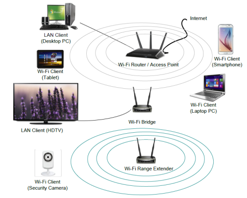 Figure 1 Typical Residential or Small Office Wi-Fi Network
Choose the Right Switching Frequency
The first requirement is at least a 1.2MHz switching frequency. Figure 2 shows a diagram of a wireless AP. The switching noise of the DC/DC converter powering the Wi-Fi core chip will affect the error vector magnitude (EVM) of that Wi-Fi modem, thus degrading the communication quality. Fortunately, standard Wi-Fi chipset phase-locked loops (PLLs) have a frequency response that can serve as a low-pass filter with a cutoff frequency at ~1MHz.
Experiments show that it’s possible to minimize this kind of EVM interference by using a high-frequency DC/DC converter. Most wireless AP chipset manufactures, like Qualcomm and Broadcom, suggested a minimum switching frequency higher than 1.2MHz, with some margin reserved.
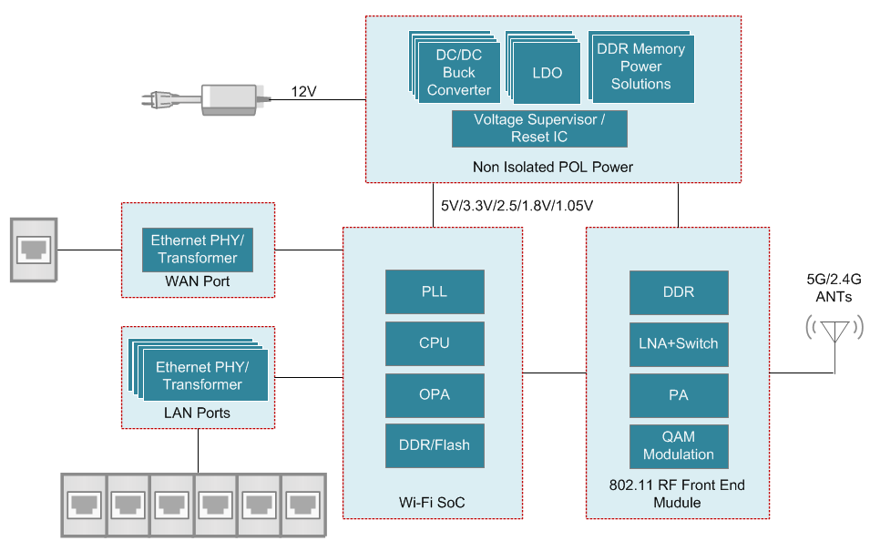 Figure 2 Diagram of a Wireless AP
To satisfy the minimum frequency requirement, you could use a converter based on current-mode control. This kind of converter usually has an internal clock to synchronize its operation. It’s not very challenging to meet a design target such as 1.4MHz with a tolerance ±200kHz. The disadvantage is the converter’s moderate load transient performance. Sometimes, to meet the fast load transient requirements of a Wi-Fi system, you have to use a larger output capacitance, which increases the total system cost.
Speed up Load Transient Response
The second requirement is the faster load transient response. The power consumption of the amplifier in a Wi-Fi block is quite different in the data transceiver and idle states, and the state change can be very fast. This imposes higher requirements on the load transient performance of your power-supply solution.
You could choose a converter with a constant on-time (COT) mode, which is famous for its faster loop response. Unfortunately, there is no internal clock in a COT converter; the converter simply generates a proper on-time for the high-side power field-effect transistor (FET) based on the input and output voltage to maintain a pseudo-constant switching frequency. The switching frequency of a COT converter changes greatly as the input and output voltage changes. It’s very difficult to design a COT converter with a relatively tight frequency tolerance requirement.
Use a Frequency Lock
You need a high-frequency, cost-effective solution that has fast load transient performance like a COT converter, but can also maintain a relatively constant switching frequency like a current-mode converter.
Figure 3 illustrates a proposed solution that adopts the D-CAP3™ control mode and implements a proprietary frequency-lock function to achieve a constant frequency like a current-mode device.
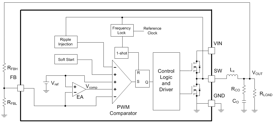 Figure 3 Block Diagram of a D-CAP3 Control-mode-based Converter
Compared with the traditional COT control mode, you can realize several benefits with this solution:
- The converter switching frequency is compared to a reference clock frequency. Based on the result, the on-time generated by a one-shot block adjusts to maintain a switching frequency within a relatively narrow variation range.
- An error amplifier removes DC voltage errors caused by the ripple amplitude of the output voltage. This DC error normally exists in a traditional COT control-mode converter.
- Instead of using the ripple of the output voltage as in a COT converter, a D-CAP3 control-mode-based converter will generate an internal ripple signal to emulate the inductor current ripple, eliminating the need for an equivalent series resistor on the output capacitor and achieving stable regulation even without output voltage ripple.
The frequency lock function makes it possible to achieve a relatively constant switching frequency. If the internal reference clock is set to 1.4MHz, you can easily guarantee a switching frequency higher than 1.2MHz in mass production, satisfying the first requirement. As to the second requirement, you can also meet a fast load transient response easily, since that is an inherent benefit of DCAP-3 control mode.
Turning Theory to Practice
Let’s take TI’s TPS563249 17V, 3A buck converter as an example to obtain the measurement result.
Figure 4 shows the faster load transient response of the TPS563249 compared to a current-mode converter. To make a direct comparison, the switching frequency of the current-mode converter is set at 1.4MHz, as is the TPS563249, and the crossover frequency is set at about one-tenth the switching frequency. Both converters are using the same 1.5µH/22µF output inductor-capacitor filter.
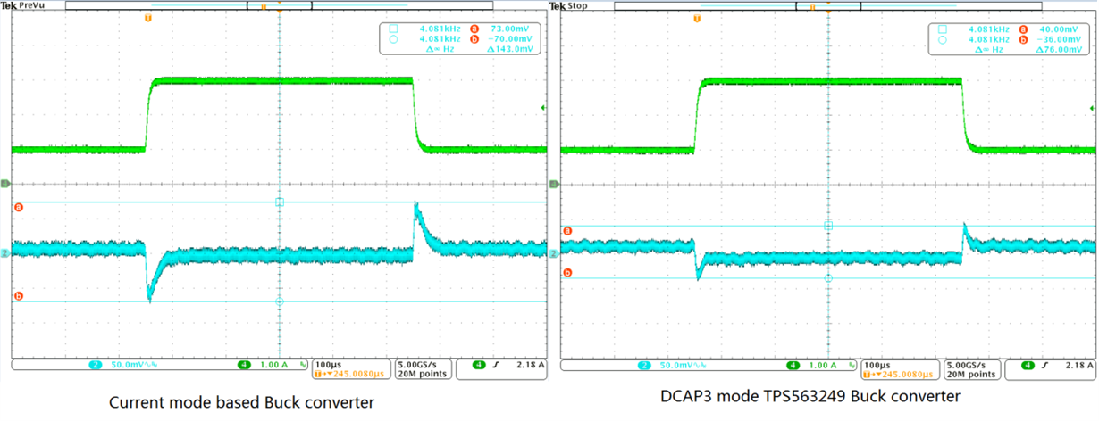 Figure 4 The Faster Load Transient Response of the TPS563249 Compared to a Current-mode-based Converter
The load step is from 1A to 3A with a 2.5A/µS slew rate; the target output voltage is 3.3V. The peak-to-peak output voltage ripple with the current-mode converter is 4.3% of the nominal output voltage, while it’s only 2.3% with the TPS563249.
Figure 5 and Figure 6 show the constant switching frequency of the TPS563249 compared to a general COT converter without the frequency lock feature.
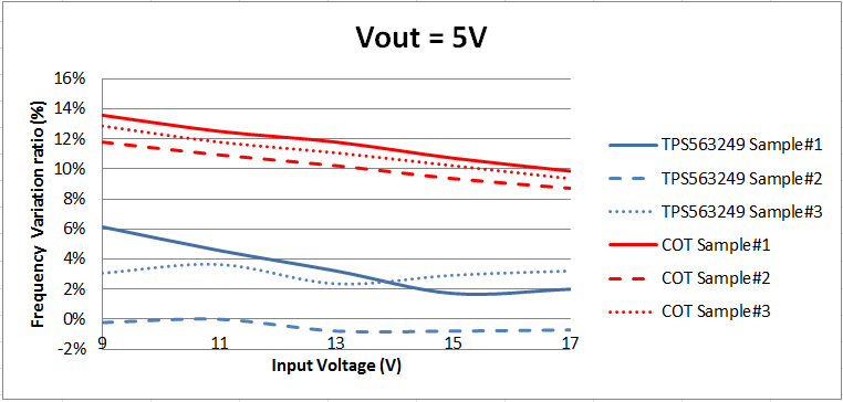 Figure 5 Frequency Variation versus a Different vIN (VOUT = 5V)
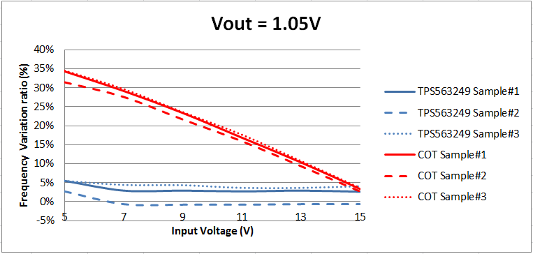 Figure 6 Frequency Variation versus a Different vIN (VOUT = 1.05V)
The TPS563249 has a smaller variation range compared to a general COT converter. As you can see, the TPS563249 also maintains a tight frequency range: there is around 5% of variation from the nominal frequency regardless of how the input and output voltage changes. However, for the general COT converter, the frequency varies ~35% from the nominal frequency in the worst case.
In general, the TPS563249 works at a constant 1.4MHz switching frequency and removes the noise interference in a Wi-Fi system for all conditions. It also satisfies the fast load change requirement from a Wi-Fi amplifier by implementing D-CAP3 control mode.
The 1.4MHz high switching frequency is helpful to minimize total system size, as well as bill-of-materials cost. It’s quite suitable for frequency-sensitive applications, such as broadband modems, routers and gateways with wireless AP.
Additional Resources
- Download the TPS563249 data sheet.
- Watch our training video: Power Tips: DCAP vs. Voltage Mode.
- Read these blogs: