SSZT635 august 2018 CC3220SF , UCC24650 , UCC28730
Some appliances, especially those plugged into AC power, continue to draw electricity even after you have ostensibly shut them down. In fact, 5-15 percent of the energy consumed by a home is from appliance standby power. Energy-saving technology helps keep standby power at a zero power level while always connected to Wi-Fi®, which will be a top trend in next-generation appliances.
International Electrotechnical Commission (IEC) 62301:2011 specifies methods of measuring electrical power consumption in standby and relevant low-power modes (off mode and network mode). These methods apply to electrical products with a voltage range that lies wholly or partly between 100VAC and 250VAC for single-phase products and 130VAC and 480VAC for other products. Clause 4.5 of IEC 62301:2011 classifies measurements of less than 5mW as zero power, which is now the basis for a zero-power marketing campaign as a target for no-load standby power dissipation in electronic devices and appliances. Products meeting this IEC requirement can earn a zero power label.
Most home appliances need a bias power supply and dual power rails for the entire system of 3.3V for the system controller and 12V for the power module. Figure 1 shows the 15W Dual Isolated Output Bias Power Supply with 4mW Zero Standby Power Consumption Reference Design, which provides dual isolated outputs of 3.3V and 12V while also achieving very low power consumption in standby mode: 3mW at a 115VAC input and 4.4mW at a 230VAC input. This reference design is a good fit for isolated offline systems that require minimal standby power, high efficiency and fault protection.
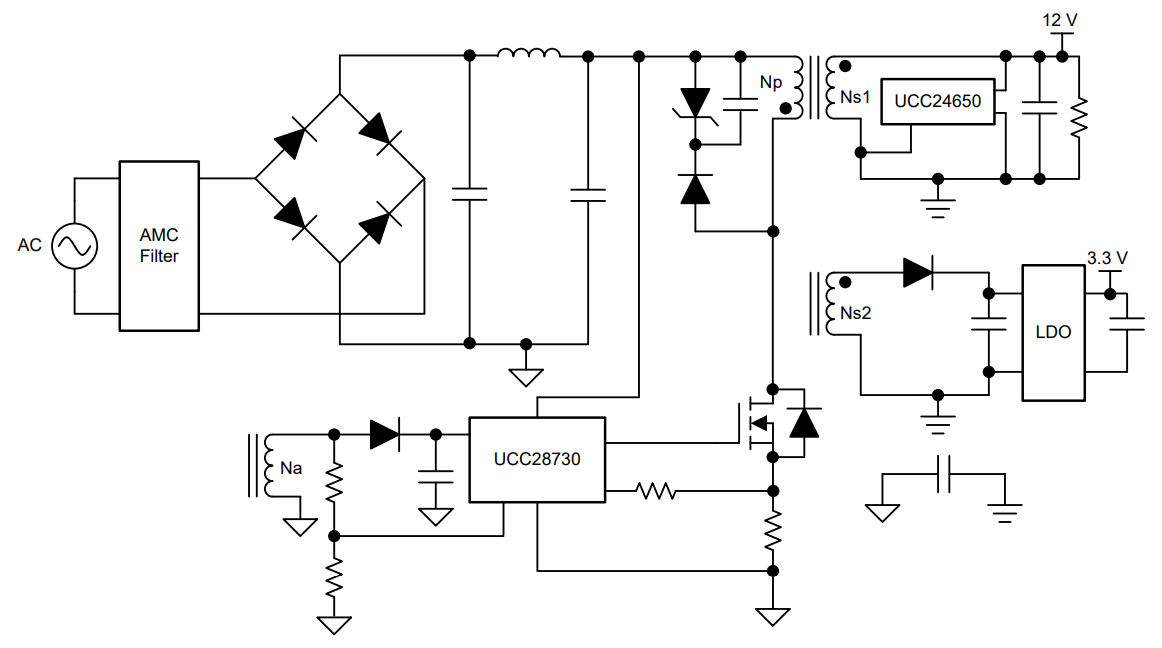 Figure 1 Block Diagram of the 15W Dual
Isolated Output Bias Power Supply Reference Design
Figure 1 Block Diagram of the 15W Dual
Isolated Output Bias Power Supply Reference DesignThe traditional method of achieving zero power is to use a mechanical switch or relay to cut the main power path. But this method does also cut off the power to Wi-Fi or any touch keys or proximity sensors that are typically expected to wake up the system when needed. The reference design in Figure 1 shows the basic power supply topology to achieve zero standby power. It keeps whatever minimal functionality and components such as the microcontroller (MCU), touch key controller, any sensors, Wi-Fi, light-emitting diode (LED) driver or any other parts required alive even during standby and allows for multiple wake-up options that way. Accordingly one could divide the system into two portions: ‘active during standby’ and ‘active during ON’.
Depending on the system configuration there are two options to design the power tree. For one of the options Figure 2 shows the block diagram of a single power supply system with an extra standby path.
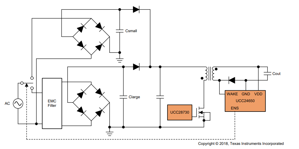 Figure 2 Block Diagram of a Single
Power Supply System with Extra Standby Path
Figure 2 Block Diagram of a Single
Power Supply System with Extra Standby PathDuring normal operation, the system in Figure 2 operates with electromagnetic interference (EMI) filter circuit and a large capacitor (Clarge) that has a larger leakage current. In standby mode, UCC28730 flyback controller work under very low switching frequency (32Hz), the ENS pin of the UCC24650 voltage monitor switches the relay to an extra standby path, which operate with a small capacitor (Csmall) that has much less leakage current and no EMI filter.
For major appliances with higher power capabilities Figure 3 demonstrates the second option where the power tree is separated into a high power path that includes power factor correction (PFC), DC/DC converter and a DC/AC inverter and the auxiliary power supply.
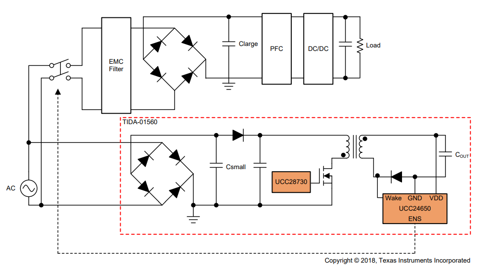 Figure 3 Block Diagram of Power
Converter System with Bias Power Supply
Figure 3 Block Diagram of Power
Converter System with Bias Power SupplyDuring ‘ON’ mode a UCC28730 flyback controller serves as the auxiliary power supply for main power stage. During standby mode, the ENS pin of the UCC24650 shuts off the relay and disconnects the main power stage. Only the flyback converter is connected to the power line.
Wi-Fi is a key technology for the Internet of Things (IoT), and one of key features of smart appliances is remote control via a wireless connection or the cloud. Thanks to latest advancements in technology it is possible to achieve zero power standby even for systems with Wi-Fi in ‘always connected’ mode.
In order to verify and test this a SimpleLink™ Wi-Fi CC3220SF wireless MCU LaunchPad™ development kit is powered by the 15W dual isolated output bias power supply with 4mW zero standby power consumption reference design and configured in “always connected” low-power mode while connected to an access point. In this mode, the device can enter deep sleep mode, in which voltage levels are lowered, fast clocks are off and memories are in retention mode. To keep the connection with the access point between two sockets, a special beacon maintains contact during every long sleep interval. Figure 4 shows a system that uses the reference design to power Wi-Fi. The system uses the 3.3V output and the 12V output has no load. The IMETER-BOOST evaluation module (EVM) monitors the current of the 3.3V power supply, an AC source provides VACIN and a digital power meter monitors the power consumption of the whole system. Figure 5 shows the AC input power consumption.
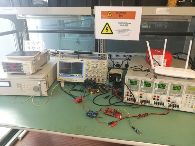 Figure 4 The System Powering Wi-Fi and
Meeting Zero Standby Power
Figure 4 The System Powering Wi-Fi and
Meeting Zero Standby PowerWhen the input voltage is 110VAC, the standby power is 3.86mW; when the input voltage is 230VAC, the standby power is 4.217mW. This system’s standby power is thus below 5mW and can earn a zero power label.
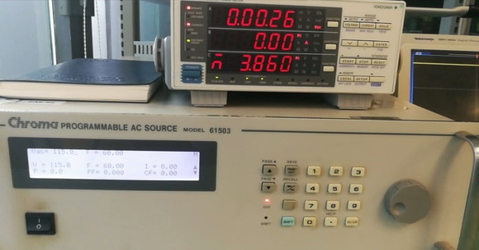
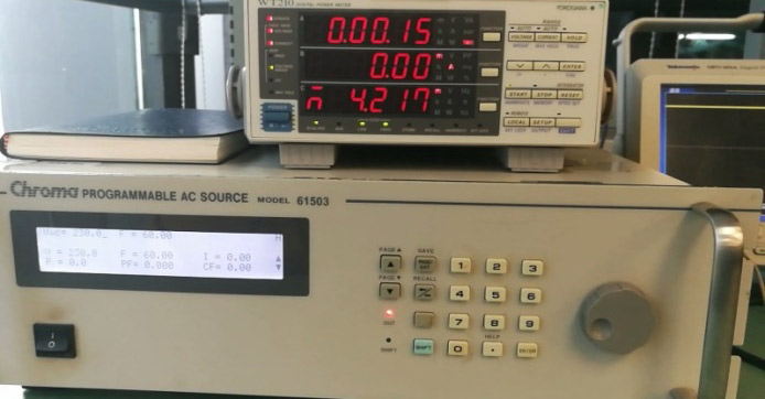 Figure 5 Standby Power Test Results
under 110VACIN And 230VACIN
Figure 5 Standby Power Test Results
under 110VACIN And 230VACINEnergy standards such as the Department of Energy Clean Energy Standard Tier 2 and Level VI Energy Efficiency are becoming more strict. These standards drive the need higher efficiency and lower standby power in appliance applications. The 15W power supply reference design demonstrates how the UCC28730 can provide ultra-low standby power without sacrificing startup time. It leaves enough margin from the 5mW power budget to enable ‘zero power standby’ with several wake-up options including Wi-Fi while lowering power usage over the universal input.
Additional Resources
- Learn more about TI products for your next-generation appliance designs.
- Read these blog posts: