SSZT669 july 2018 ISOW7842 , MSP430F5172 , TMP116 , TPS92515HV , TPS92561
In a previous blog post, I introduced a LED Lighting Control Reference Design for Machine Vision. In this post, I’d like to elaborate a bit about it, following the same modular approach that our team followed during the design process.
Easily Digestible Tidbits
During the design process, we packaged details into smaller subcircuits and gave those blocks descriptive names, as shown in Figure 1. This helped us convert our ideas into the actual circuit.
 Figure 1 Modular Approach of the Reference Design
A Round Trip through the Reference Design
Let’s start with the Common Power block. To be honest, this is the circuit block where I needed to leave its name a bit vague, because the Common Power block is a smorgasbord of at least seven different functions.
Rumor has it that I simply put all seven functions into this block because I didn’t know where else to put them. Not true: all of these functions relate to power. The Common Power block is the home of common devices and functions like the 5V buck, the 3.3V low-dropout regulator (LDO), the 2.5V reference and the electromagnetic interference (EMI) filter.
If that isn’t exciting enough, I put also a TPS26602 eFuse into the block. This device takes care of the power input and provides almost lossless reverse input protection. The team even figured out how to change the current limit of this eFuse on the fly. This adaptive input current limit enables a constant systems input power limit of 15W over the 8V-to-36V input voltage range. One channel of a dual digital-to-analog converter (DAC) provides the control voltage for this feature.
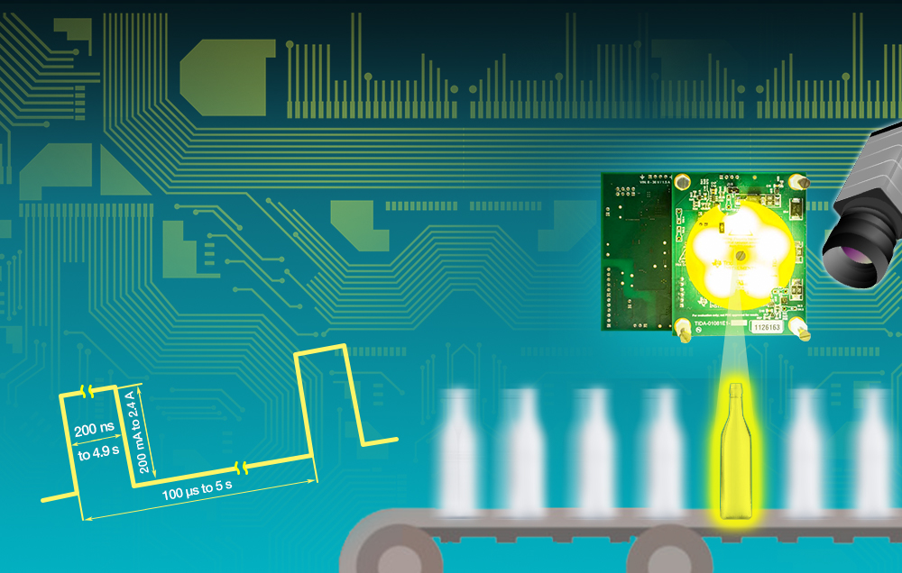
Moving along, the LED Buck and LED Board blocks combine LED-related functionality. They support the ultra-short 200ns LED strobes with constant currents up to 2.4A and pulse repetitions up to 10kHz. Driving a string of five white high-power LEDs results in 40W of pulse power at a 2.4A current level. The reference design supports longer pulse times (up to continuous LED operation), lower LED currents and lower frame rates too. Short rise and fall times of the LED current and a short and constant trigger delay of 10µs are enabled by both a special control scheme and by the 48V used to power the TPS92515HV LED buck converter.
Four TMP116 temperature sensors supervise the board temperatures; these sensors are able to switch off the LEDs and other components to protect the system. Each of the temperature sensors provides 64 bits of user-programmable electrically erasable programmable read-only memory (EEPROM) to identify modules or store calibration data.
A dedicated LED cover plate minimizes the risk of eye injury.
Are you confused by the 40W of LED power from a 15W of system input, or asking yourself what we did with the remaining channel of the dual DAC? Let me explain by discussing the Pre-Boost block, another tricky circuit. The pre-boost provides the 48V (used by the LED buck) from the 8V-to-36V system input voltage. The output of this subcircuit is buffered by a bank of capacitors to support the 40W pulses. The pre-boost operates with an adaptive average input current limit (controlled by the second channel of the dual DAC) and consumes a constant 10W when enabled.
Looking at the LED lighting control reference design schematic, you might wonder why we used a phase-dimmable, single-stage boost controller like the TPS92561. The answer is because of its simple input current control.
Compared to all of the modifications we made for these blocks that I’ve described so far, the remaining two circuit blocks do what their names imply. The Microcontroller (MCU) block contains a MSP430F5172 MCU with a high-resolution timer and provides main control for the complete reference design, including supervising, monitoring, timing and communication with a terminal program on a user’s PC.
The Isolated Power and Data Interface block includes an ISOW7842 digital isolator with integrated power converter and breaks undesired ground loops and provides a solution for trouble-free external triggering and communication.
Figure 2 graphically depicts everything I’ve explained so far.
 Figure 2 Simplified Block Diagram of the Reference Design
As you can see, only two of the six blocks have a strong tie to LED lighting. That is why I hope that my explanation will inspire you to reuse these subcircuits in other designs and other applications. For more details, feel free to have a detailed look at the documents provided with this LED lighting control reference design.