SSZT743 april 2018 TLV9061
Voice commands are a popular feature in many applications as a way to differentiate products in the market. Microphones are a primary component to any voice- or speech-based system and electret microphones are a common choice in applications for their small size, cost and performance.
This blog post continues our series on high-performance, cost-sensitive circuits and describes the design of a very small, cost-optimized electret condenser microphone pre-amplifier. The design uses the TLV9061, which is the industry’s smallest operational amplifier (op amp) in a 0.8mm-by-0.8mm extra small outline no-lead (X2SON) package. Figure 1 shows an electret microphone amplifier circuit configuration.
 Figure 1 Noninverting Electret
Microphone Amplifier Circuit
Figure 1 Noninverting Electret
Microphone Amplifier CircuitMost electret microphones are internally buffered with a junction field-effect transistor (JFET), which is biased with the 2.2kΩ pull-up resistor. Sound waves move the microphone element, causing current flow into the JFET drain inside the microphone. The JFET drain current causes a voltage drop across R2 which is AC coupled, biased to mid-supply and connected to the IN+ pin of the op amp. The op amp is configured as a bandpass-filtered noninverting amplifier circuit. With the expected input signal levels and the desired output magnitude and response, you can calculate the gain and frequency response of the circuits.
Let’s walk through an example design of this circuit for a +3.3V supply with an input of 7.93mVRMS and an output signal of 1VRMS. The 7.93mVRMS corresponds to a 0.63Pa sound-level input with a microphone and a -38dB sound pressure level (SPL) sensitivity specification. The bandwidth goals are to pass common speech frequency bandwidths of 300Hz to 3kHz.
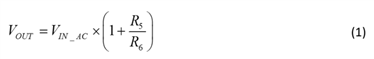
Equation 1 shows the transfer function defining the relationship between VOUT and the AC input signal:
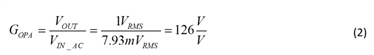
Equation 2 calculates the required gain based on the expected input signal level and desired output level:
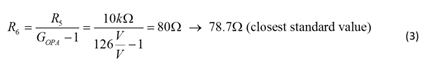
Select a standard 10kΩ feedback resistor and use Equation 3 to calculate R6:
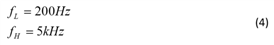
To minimize the attenuation in the desired passband from 300Hz to 3kHz, set the upper (fH) and lower (fL) cutoff frequencies outside the desired bandwidth (Equation 4):
Select C7 to set the fL cutoff frequency (Equation 5):

Select C6 to set the fH cutoff frequency (Equation 6):

To set the input signal cutoff frequency low enough so that low-frequency sound waves can still pass through, select C2 to achieve a 30Hz cutoff frequency (fIN) (Equation 7):

Figure 2 shows the measured transfer function for the microphone pre-amplifier circuit. The flatband gain only reaches 41.8dB or 122.5V/V, which is a little lower than the target due to the narrow bandwidth and attenuation between the high- and low-pass filters.
 Figure 2 Microphone Pre-amplifier
Transfer Function
Figure 2 Microphone Pre-amplifier
Transfer FunctionThe circuit was designed with TI’s X2SON package to fit on the back side of a 6mm-diameter electret microphone. This size restriction required the use of a very small op amp: the TLV9061 has a 0.8mm-by-0.8mm footprint. Resistors and capacitors in the small 0201 size also minimize printed circuit board (PCB) area, which you could reduce further by using even smaller resistors. Figure 3 and Figure 4 show the PCB layout.
 Figure 3 Microphone Pre-amplifier
Layout on the Back Side of a 6mm-diameter Electret Microphone
Figure 3 Microphone Pre-amplifier
Layout on the Back Side of a 6mm-diameter Electret Microphone Figure 4 3-D View of PCB Design,
Showing a Few Different Angles of the Microphone and PCB
Figure 4 3-D View of PCB Design,
Showing a Few Different Angles of the Microphone and PCBYou can modify the design steps described above to fit different microphone sensitivities. Be mindful when designing with small amplifiers like the TLV9061 to follow the layout best practices described in this application note, “Designing and Manufacturing with TI’s X2SON Packages.”
Additional Resources
- Download the TLV9061 data sheet.
- To simplify and speed system design, download the “Analog Engineer’s Circuit Cookbook,” which includes a comprehensive library of subcircuits.
- Find commonly used analog design formulas in the “Analog Engineer’s Pocket Reference.”