SSZT929 october 2017 BQ25890
When you plug in your smartphone to charge, you want it to charge as fast and safely as possible. The integrated circuit (IC) that a smartphone (or other mobile device) cable plugs into is typically a battery-charger IC like the one shown in Figure 1. This IC powers the phone and charges the battery so that it can power the system in the absence of an adapter.
 Figure 1 Wall Adapter and
Battery-charger IC
Figure 1 Wall Adapter and
Battery-charger ICIf you’re like me, when you are desperate to charge your phone, you’ll choose any available USB source and/or random cable to charge the battery. If you’re using a lower-power wall adapter (source) or a lower-quality cable, most chargers will reduce the charge current in order to prevent the input source current from exceeding a preset maximum value or the source voltage from dropping below a preset voltage.
These preset voltages and current limits may not be the optimal voltage for the USB source/cable combination, however, and thus the source will not provide the maximum possible output power. It’s no surprise that the more power the source provides to the battery-charger IC, the faster the battery will charge. Ideally, the charger has an algorithm to seek out the source’s maximum power if you’re using an arbitrary, possibly non-USB compliant or third-party adapter and cable combination.
The charger’s preset maximum current varies depending on the type of source. When charging from a legacy USB source, many charger ICs use the USB data lines (D+, D-) to detect the type of USB source (standard downstream port [SDP] or charger downstream port [CDP]) and its corresponding maximum current capability – at least until the USB host is enumerated and can provide more information about the source’s true current capability.
If the IC doesn’t detect a USB source, the source may be a proprietary adapter with its own maximum current capability. Standard “wall-wart” adapters without communication capabilities (dedicated charging port [DCP] adapters) can have a wide range of current capabilities. The charger’s input-current feedback loop (IINDPM) uses the detected current capability to prevent the charger from pulling more input current.
While a legacy desktop/laptop USB port provides only 5V with a known tolerance, newer USB ports and adapters with USB-compatible cables provide even higher voltages with difference tolerances. If the source or adapter cannot provide its rated current, or if you’re using a third-party adapter or a highly resistive (low-cost or extra-long) power cable from the source to the smartphone, then the charger IC’s input voltage and available power drops. In such cases, the charger’s second line of defense against adapter crash and/or oscillation into/out of charging is its input voltage feedback loop (VINDPM), which further reduces the charger’s input current to prevent the input voltage from dropping below a fixed threshold.
Relying on initially detected current settings and present voltage thresholds to obtain maximum power from a power source and cable combination rarely results in the charger extracting optimal power from the source. An input current optimizer (ICO) circuit intelligently identifies and resets the maximum or optimal current (IOPT) that the charger can pull from the power source and cable combination to achieve the fastest possible charge time without collapsing the source.
Figure 2 illustrates the basic operation of the ICO algorithm. The charger pulls increased current until the adapter voltage drops to the VINDPM setting. The charger then takes one input current step back, setting the IINDPM threshold to IOPT.
 Figure 2 ICO Algorithm
Illustration
Figure 2 ICO Algorithm
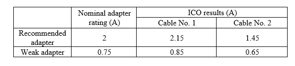
IllustrationTable 1 shows two different adapters with different current ratings powering a bq25890 through two different USB cables. Cable No. 1 is a high-quality cable with low resistance. Cable No. 2 is a low-cost, extra-long cable with higher resistance.
|
Cable No.1 is the recommend, high quality cable. Cable No. 2 is the longer, and therefore more resistive, cable. The ICO circuit detects the real capability of both adapters when powered with cable no. 1. The detected current is slightly higher due to the adapter’s output power tolerance. The current delivery capability is reduced using cable no. 2, but the ICO circuit still detects it. Thus, chargers with ICO provide the best solution on the market to optimize the utilization of adapter power with an arbitrarily selected cable.
When our phones’ batteries are in the red, we all pick the first available adapter source and cable to charge them. A charger with ICO circuitry, like chargers in the bq25890 family, can find the maximum output power capability of most adapter/cable combinations for the fastest battery charging, without adapter overload.
Additional Resources
- For more detail about IINDPM and VINDPM feedback loops, download the application report, “Dynamic Power-Path Management and Dynamic Power Management.”
- For more detail on the ICO feature, read the application note, “Extracting Maximum Power From an Adapter Without Overload Using the bq2589x Battery Charger’s ICO Feature.”