SSZTAC0 march 2017 LM5170-Q1
The 48V-12V dual-battery power system is becoming popular for mild hybrid electric vehicles. The vehicle’s dynamic operating conditions may require the transfer of electric power as high as 10kW back and forth between the two battery rails. Because of all sorts of operation scenarios in a moving vehicle, controlling the power flow needs in one direction or the other in real time can be a rather intricate task that demands the intelligence of a digital control scheme. So when leading automakers and tier-1 suppliers started developing 48V-12V bidirectional power converters, most of them took a full digital approach.
Full digital solutions are costly because they require many discrete analog circuits. These analog circuits include precision current-sense amplifiers, power MOSFET gate drivers, monitor and protection circuits, and so on. Discrete solutions are also bulky and less reliable due to the large device counts on the circuit board. To reduce solution size and lower cost while improving performance and system-level reliability, some tier-1 suppliers are looking into a mixed architecture where a microcontroller handles higher-level intelligent management, and highly integrated analog controllers implement the power-converter stage. In this post, I’ll discuss how to identify the most suitable control scheme for such an analog controller.
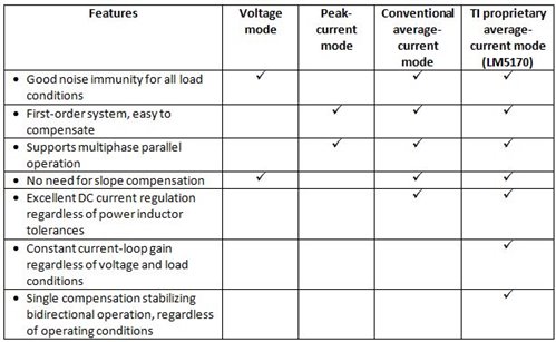
Table 1 summarizes the advantages and disadvantages of different control schemes.
|
A 48V-12V bidirectional converter normally must have highly accurate current regulation (better than 3%) in order to precisely control the amount of power delivered from one battery rail to the other. Owing to high power, the system usually requires multiphase circuits in an interleaved parallel operation to share the total load, and the sharing should be evenly balanced among individual phases. Therefore, the voltage-control mode is not suitable because of its inability to achieve multiphase sharing.
The peak current-mode control scheme, which generates a pulse-width modulation (PWM) signal based on the peak inductor current, can achieve multiphase sharing. However, the sharing balance is largely affected by the power inductor tolerances. The power inductor usually has a tolerance of ±10%, leading to remarkable sharing errors, thereby causing unbalanced power dissipations in different phases. What’s worse is that the peak current of the inductor has an inherent error from the DC current, leading to less accurate current regulation and thus less accurate power delivery.
The conventional average current-mode control scheme solves the current-error problem of peak current-mode control because it regulates the averaged inductor current and eliminates the effects of inductor tolerances on current regulation. However, the power plant transfer function varies with the operating voltage and current conditions, and bidirectional operation requires two different loop compensations.
In order to overcome the challenges with a conventional average current-mode control scheme and simplify real circuit implementation, TI developed an innovative average current-mode control scheme for 48V-12V bidirectional converter operation, as shown in Figure 1 and Table 1. The power stage consists of:
- A high-side FET (Q1).
- A low-side FET (Q2).
- A power inductor (Lm).
- A current-sense resistor (Rcs).
- Two batteries, one at the HV-Port and the other at the LV-Port.
The control circuit comprises:
- A gain-of-50 current-sense amplifier with direction steering by the direction command DIR (“0” or “1”).
- A transconductance amplifier serving as the current-loop error amplifier, with a reference signal (ISET) applied at the noninverting pin to set the phase DC current regulation value.
- A PWM comparator.
- A ramp signal generated in proportion to the HV-Port voltage.
- A steering circuit controlled by DIR to apply the PWM signal to control either Q1 or Q2 as the main switch.
- A loop compensation network at the COMP node.
Rcs senses the inductor current, and the signal is amplified by 50 times. The signal is sent to the inverting input of the transconductance amplifier, resulting in an error signal at the COMP node, which is also the node of the noninverting input of the PWM comparator. Comparing the error signal with the ramp signal produces the PWM signal. Steered by the DIR command, the PWM signal can control the Q1 for buck-mode operation and force the current flow from the HV-Port to the LV-port, or when sent to Q2, reverse the direction of current flow.
 Figure 1 TI’s Proprietary Average
Current-mode Control Scheme for a Bidirectional Current Converter
Figure 1 TI’s Proprietary Average
Current-mode Control Scheme for a Bidirectional Current Converter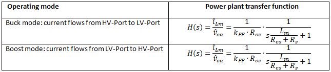
|
Table 2 shows the advantages of the new control scheme. The power plant transfer function is the same for bidirectional operation, and it is a first-order system. In addition, the transfer function is independent of the operating conditions such as the port voltage and load current levels. Therefore, applying a single Type-2 compensation network will always stabilize the bidirectional converter under all operating conditions, greatly simplifying real circuit implementation and enhancing performance.
TI’s proprietary averaged current-mode control scheme is suitable for an automotive 48V-12V bidirectional current controller. It requires a single Type-2 compensation network to cover bidirectional operation regardless of operating conditions. Current-regulation accuracy – despite the inductor tolerances, naturally multiphase parallel operation to evenly share high power, etc. – will greatly simplify a bidirectional converter design with high performance. TI has implemented this control scheme in the LM5170-Q1 multiphase bidirectional current controller. Read the blog post, “Interconnecting automotive 48V and 12V rails in dual battery systems,” to learn how to overcome the challenges of designing a power supply for hybrid electric vehicles.