SSZTAJ2 december 2016 LDC0851
When customers are designing proximity-switch applications using inductive sensing devices like the LDC0851 switch, they often ask me how to design a coil for a given switching distance. Today, I want to show you how to use TI’s new WEBENCH® tool to make these calculations, provide computer aided design (CAD) files for coil layout, and then build and test a prototype for a proximity application in three easy steps.
I will use the example of an open/close lid application from a previous blog post. A simplified diagram is provided below for reference.
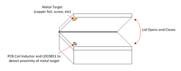 Figure 1 Lid Open and Close Detection
with LDC0851
Figure 1 Lid Open and Close Detection
with LDC0851To access the WEBENCH tool, go to the LDC0851 product page and navigate to the on/off sensing tool on the right, as shown in Figure 2. Alternatively, simply type www.ti.com/ldc0851webench into your browser.
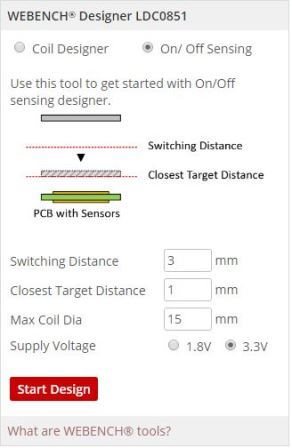 Figure 2 Inductive Sensing WEBENCH
Tool for Proximity-switch Applications
Figure 2 Inductive Sensing WEBENCH
Tool for Proximity-switch Applications- Enter the relevant parameters
and click Start Design.
- Switching Distance: This is the distance at which you would like the LDC0851 to change output states in the presence of a metal target. For this application, the switching point should occur at 3mm.
- Closest Target Distance: Because this is a contactless switching technology, a robust design will allow the metal target to continue to move closer to the coil after it has crossed the switching point. Entering this parameter will determine the minimum inductance of the sensor coil. For this application, once the lid is completely closed, it will rest on a 1mm-thick plastic barrier.
- Max Coil Dia: This is the maximum diameter that you have room for on your printed circuit board (PCB). Longer switching distances will require a larger coil diameter. Increase this parameter if you would like to see more results. This application only has enough room for a 15mm coil at maximum.
- Supply Voltage: This parameter impacts the supportable minimum inductance. Using a supply of 3.3V can support sensor inductances lower than 1.8V. This application supports the use of a 3.3V supply. Refer to Figure 9 and 10 of the LDC0851 data sheet for more information. There is also a design space calculator available on the “LDC0851_calc” tab in the inductive sensing design calculator tool.
- Click Start Design.
- Select appropriate coils for
your application by filtering and then clicking Open Design. Following along
with the numbered boxes shown in Figure 3:
- Solution type: Stacked coils can provide a more compact layout, but typically provide less switching distance than side-by-side coils for the same diameter. If no results are showing for a stacked coil design, select “side-by-side” or “both” and then click “recalculate.” This application can support a four-layer PCB design, but requires a stacked coil layout due to limited available PCB area.
- See Filter Results on the top right to view the settings that your PCB vendor can easily support. For the chosen application, use a trace width of 5mil and a four-layer PCB.
- Click Open Design.
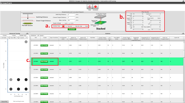 Figure 3 Select a
Design
- Verify that the operating values are correct for the application, which is shown on the bottom left of Figure 4.
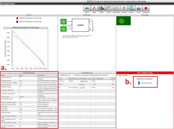 Figure 4 Open Design
b. Click CAD File Export, shown on the bottom right of Figure 4, and choose from a variety of CAD tools to open the design, as shown in Figure 5.
 Figure 5 CAD Export Tools
c. Download and open the file. Add any finishing touches to the PCB, as shown in Figure 6.
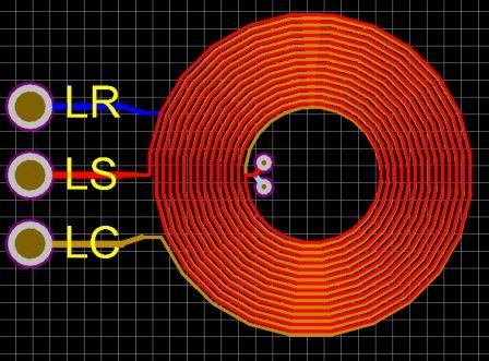 Figure 6 Open up the Coil Layout and
Add Final Touches
Figure 6 Open up the Coil Layout and
Add Final Touchesd. Finally, the design is ready to be packaged up and sent for quote.
Prototype and Testing Phase
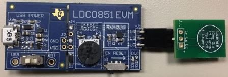 Figure 7 Build Design and Prototype
To test the switching distance I connected a flat metal target to a linear position motor and swept the target metal back and forth over our prototype to find the switching distance versus the adjustment (ADJ) code. Figure 8 shows that I achieved a switching distance of 3mm for an ADJ setting of 1. A simple way to set this ADJ value is to use Table 1 from the LDC0851 datasheet. For an ADJ setting of 1 it is recommended to use a resistor divider of 49.9 kΩ and 3.32 kΩ which are common resistor values.
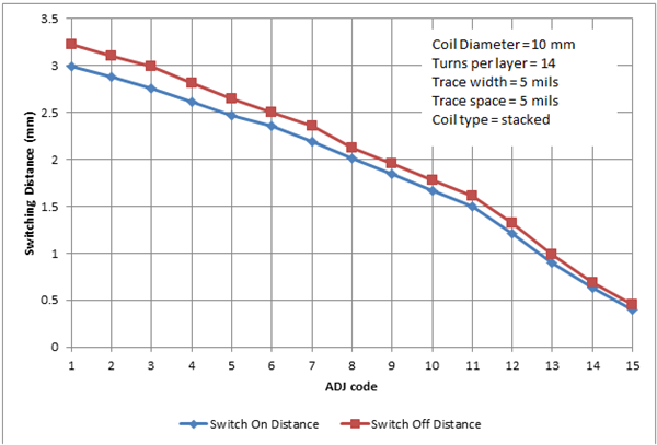 Figure 8 Switching Distance Curve
This design is ready for use in our lid open/close applications and meets the original requirements of 3mm switching distance with our specified PCB constraints.
Now you can say that proximity switch applications can be as easy as 1, 2, 3 with WEBENCH® on/off inductive designer. What are your experiences designing proximity-switch applications? Log in to comment below.
Additional Resources
- Learn more about inductive sensing applications and explore the Tools & software, Technical documents, and Support & training
- Read these relevant inductive sensing blogs: