SSZTAJ7 december 2016
In part one of this series, I discussed a TI reference design used for predictive maintenance with respect to filter changes. One of the most obvious questions that comes to mind is, “How can this design be implemented on any system and still give accurate results?” The most logical way (no pun intended) is to implement a software-based algorithm that is directly responsible for defining the typical operating conditions of a heating, ventilation, and air conditioning (HVAC) system.
In order to develop this algorithm, let’s first define the environmental variables that will play a part in system-input changes:
- Operating temperature: the temperature of air across the evaporator coil can be affected by the refrigeration charge, or a blower that is moving air across the evaporator too fast or too slow. This variable changes the temperature slightly in either direction; but nevertheless, you must account for it.
- A temperature drop due to air conditioning: once the system nears the end of a refrigeration cycle, the temperature reading of the sensor will be lower than it was on startup. This is caused by the approach of thermal equilibrium between the air and the evaporator coil fin temperature, as the system absorbs less heat.
- Air velocity: The air velocity across the evaporator coil is dependent on the rotational speed of the motor. Any motor speed variation from system to system can therefore throw off a normal sensor. A static airflow sensor with a factory-set threshold can lead to false alerts – or even worse, no alerts at all.
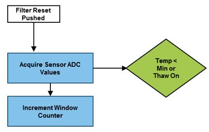
There are countless other variables I could include in this list, but for the sake of simplicity, let’s use these as the primary variables of the system and build up the first part of the logic, as shown in Figure 1.
 Figure 1 Software Algorithm Stage
1
Figure 1 Software Algorithm Stage
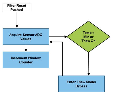
1Once the system is running and the user presses the reset button on the board, the first thing the system will do is begin taking analog-to-digital converter (ADC)readings from the sensors: in this case, two piezoelectric vibration sensors and a single analog output temperature sensor. I’ve also included a counter for averaging purposes down the road in the design. The first decision the algorithm makes is based on the temperature. Because the lack of airflow through a dirty filter can ultimately cause the evaporator to freeze up, you have to address that issue first. You want to make sure that the temperature stays above freezing, or, if the system is frozen, that it cannot run again until it reaches a suitable thaw temperature. I’ve added a thaw mode in the event of a frozen coil – the worst-case scenario. Figure 2 shows the updated algorithm.
 Figure 2 Software Algorithm Stage
2
Figure 2 Software Algorithm Stage
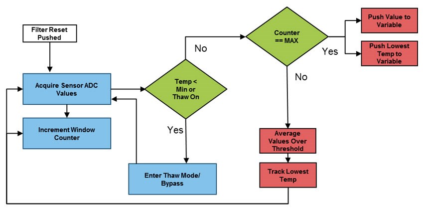
2Now, let’s compare the ADC value to an absolute threshold based on freezing conditions. This can be a static threshold because, in any system, freezing is freezing. As stated earlier, if this worst-case situation occurs, the system will automatically go into a thaw mode where the user can release the condenser contactor power, thus disallowing additional freezing in the system. The temperature sensor value is what’s important at this point, so the sensor polling is now only focused on that. The thaw temperature is a quasi-static variable that can be set based on how long the user wants the system to remain disabled after an evaporator freeze. Now that I’ve addressed the possibility of a frozen coil, I can add the rest of the logic for the airflow sensors. Figure 3 shows the final flow for this simplified calibration algorithm.
 Figure 3 Software Algorithm Stage
3
Figure 3 Software Algorithm Stage
3This final iteration adds a conditional statement for the internal counter, along with the respective action for each case. This is where the heart of system calibration occurs. Assuming that there are no freeze conditions in the system, the ADC values for each sensor are pushed into local software variables. If the counter limit is not reached, the value read for each sensor is added to the previous variable value and averaged. For the temperature, the variable is only modified when the sensor reads a lower temperature value than the current one.
As far as the counter’s maximum variable, it is up to the user how many samples to take during the calibration period. A longer sample period can provide more accurate conditions than a short sample period.
Once the counter limit is reached, the obtained values are pushed to variable values for comparison against future cycle values. Once the threshold is crossed – say for a minimum differential, as in the HVAC Coil Airflow Sensor Reference Design for Predictive Maintenance in Air Filter Replacement, the system alerts the homeowner of an airflow issue. This simplified calibration can be used in conjunction with more complex main algorithms to increase maintenance prediction accuracy.
Additional Resources
- Read the first post in this series, “Predictive maintenance solutions for HVAC filter replacement – part 1.”
- Learn more about HVAC system controller trends.
- Read the white paper “Making factories smarter, more productive through predictive maintenance.”