SSZTAL2 november 2016 PCA9306 , TCA9617B
I trust Internet search engines as my first source to provide me with reliable and quick answers, so when I first encountered the I2C protocol, I asked my trusted-source to help out. My search responded with: the Inter-Integrated Circuit (I2C) protocol is a bi-directional two-wire serial bus that provides a communication link between integrated circuits. This stated the obvious, but I still had so many more questions: What is it really? What type of devices use I2C? How will I2C help me solve real problems in my system?
I2C is a popular communication protocol that enables a master device such as a processor, microcontroller (MCU) or application-specific integrated circuit (ASIC) to communicate with other peripheral devices on the same two-wire bus. One line is dedicated for data transmission and the other for a clock signal. Think of it like a two-lane highway: each lane has cars flowing from one end to the other, just as a data packet would be transmitted from the master (processor, MCU, ASIC) to the peripheral device (temperature sensors, humidity sensors and more).
So that’s what I2C actually is … now, why would you want to use it? I2C makes it easy to implement multiple peripherals on the same bus – for example, using various sensors to monitor the temperature of a server. The I2C protocol was actually designed to support multiple devices on a single bus, while other protocols like serial peripheral interface (SPI) were designed for point-to-point single-device support. The two-wire I2C interface can also help simplify routing versus the four-wire SPI interface and reduce general-purpose inputs/outputs (GPIOs).
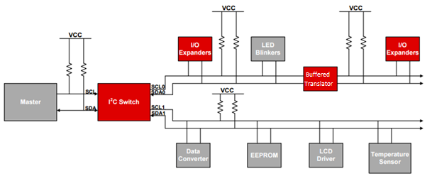
TI’s portfolio for building your I2C tree can be separated into three functions, as shown in Figure 1: buffered translators, I/O expanders and I2C switches.
 Figure 1 An Electronic System with
Various I2C Functional Devices
Figure 1 An Electronic System with
Various I2C Functional DevicesI2C buffered translators can help when your design encounters degraded signals over a long trace and/or voltage mismatch between integrated circuits (ICs). For example, if you find that you have a voltage mismatch between a 3.3V MCU I2C I/O and a 5V temperature sensor, you can use an I2C voltage translator such as the PCA9306. Additionally, with that same voltage mismatch over a long trace, you can use a buffered translator such as the TCA9617B to address the voltage difference while outputting a refreshed signal.
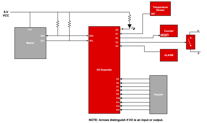
I2C I/O expanders do exactly as the name suggests – they expand the number of I/Os when your selected processor runs out of available ports, as shown in Figure 2. These devices differ from standard GPIO expanders because they communicate directly with devices on the I2C bus. This portfolio also offers a variety of features depending on your specific system needs, such as channel count, reset pins and level-shifting.
 Figure 2 A Microcontroller or Processor
Using an I/O Expander to Control Peripherals
Figure 2 A Microcontroller or Processor
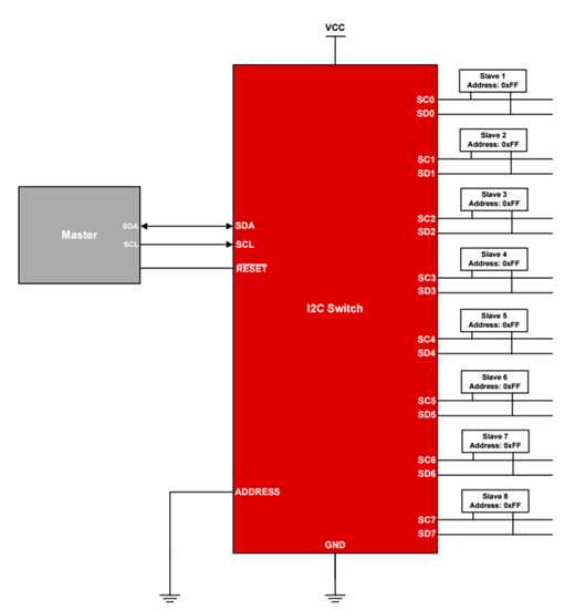
Using an I/O Expander to Control PeripheralsI2C switches can solve two different problems. The first problem is related to address-conflicts that commonly occur when two devices on the same bus have the same address. If a system has two temperature sensors and two humidity sensors on the same I2C bus – all with the address 0xFF – an I2C switch can switch to a single sensor at a time; see Figure 3. The second problem is related to power consumption. I2C switches power only one portion of the I2C bus at a time, thus keeping unused portions of the bus powered down when not in use.
What initial internet searching will try to tell you is that I2C makes it easy for system designers to implement robust system controls. Not only is this a useful protocol, but there are many device functions that can benefit your system. You can use buffered repeaters, I/O expanders and I2C switches to enhance, extend and modify your I2C bus implementation in order to meet your unique design objectives. For more information on I2C design, read “Understanding the I2C Bus.”
 Figure 3 I2C Switch Example
with Eight Channels
Figure 3 I2C Switch Example
with Eight ChannelsAdditional Resources
- Learn more about TI’s portfolio of I2C buffered translators, I/O expanders and switches.