SSZTAO5 november 2016 TPS82085 , TPS82130

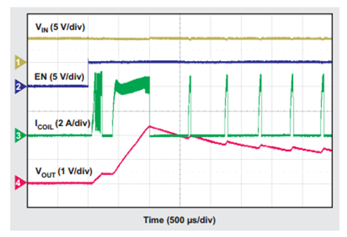
Oops. I attached my field-programmable gate array (FPGA) to the output of my DC/DC converter and now the DC/DC won’t start. When I look at the circuit with an oscilloscope, I see Figure 1. The output voltage just doesn’t enter regulation. What went wrong?
FPGAs present some unique challenges for their power supplies. For example, FPGA vendors typically require hundreds or even thousands of microfarads (µF) of decoupling capacitance on their input supply to maintain the required regulation of the FPGA’s supply voltage among the different frequencies of transients produced by the FPGA, as well as to reduce ripple on the supply voltage. Many FPGAs also require a specific startup time (not too fast and not too slow) and startup monotonicity (with VOUT reaching its set point in a straight line without any downward movements).
In addition to FPGA-related design challenges, more and more FPGA designers must also design the power supply for their FPGA. Being FPGA experts, many of these designers have little experience in power-supply design and so need a very simple power supply – a power module is an obvious choice.
Power modules achieve simplicity by integrating many or all of the required passive components. Fewer components to select results in a faster and simpler design time. Control-loop compensation is one of the first things to integrate into the power module, but this constrains the design’s stable range – and with the large amount of capacitance, an internally compensated power module may not be stable. Consult the device TPS82084 data sheet and application report for guidance on stability. The DCS-Control topology used in many of TI’s TPS82xxx power modules is very stable and supports a wide range of output capacitance.
 Figure 1 Because of This FPGA’s High
Startup Load and Very-High Decoupling Capacitance, the DC/DC Converter Cannot
Bring Its Output Voltage into Regulation
Figure 1 Because of This FPGA’s High
Startup Load and Very-High Decoupling Capacitance, the DC/DC Converter Cannot
Bring Its Output Voltage into RegulationThe very small size of power modules means there are fewer pins to work with. Fewer pins means a simpler device, but also fewer features. Another feature commonly integrated into power modules is soft-start (SS) time. This time is set internally on some power modules, like the TPS82085, but is programmable with a capacitor on other power modules, like the TPS82130. A programmable SS time is generally required for meeting a specific startup time requirement and is very helpful for starting a power module with all of that capacitance connected.
But let’s get back to what went wrong. In the waveform shown in Figure 1, the DC/DC converter can’t start up when driving the FPGA and its capacitance. This application note explains the details, but here is a short summary of various ways to fix the issue:
- Delay the startup ramp with a resistor, capacitor, diode (RCD) circuit.
- Switch to a DC/DC converter with a SS pin to program the SS time.
- Use a load switch to decouple the FPGA from the DC/DC.
How Have You Overcome Startup Issues in Your past Designs?
Additional Resources:
- Use the WEBENCH FPGA Power Architect to start designing today.