SSZTB13 august 2016 CSD18532Q5B , ISO7141CC , ISO7141FCC , ISO7421 , LM5009 , LM5050-1 , LM5069 , MSP430F2112 , TLC5928 , TPS1H100-Q1
Many (if not most) machines are controlled by specialized computers called programmable logic controllers (PLCs). The roots of this trend reach back into the late 1960s when machines and assembly lines became increasingly complex, as did their corresponding control systems. The hard-wired relay-based control systems of that time were inflexible and error-prone. Maintenance was a nightmare. The horrendous amount of required relays and cabling didn’t make engineer’s lives easier. Mechanical devices like relays simply wear out much faster than well-designed electronic devices. To optimize the control systems of their assembly lines for better reliability and maintenance General Motors contracted Bedford Associates to design an electronic replacement for the various hard-wired relay based control systems. The first PLC was born. Called the MODICON-084, it is today considered the grandfather of all PLC systems. This revolutionary technology was quickly adopted industry-wide because of its flexibility, simplicity and better cost structure.
In the following years PLCs shrunk to smaller form factors and programming became easier. More PLC vendors appeared and a standardization of the programming and feature sets occurred. Today there is a large infrastructure of PLC systems with functions and features for nearly all situations in automation and process control.
The main benefits of PLC-based control systems namely flexibility and simplicity might now motivate the user of a machine to optimize his work flow. Changing the software can increase machine speeds or reduce the cycle time of a production process. Time is money! As a consequence, however, machines wear out more quickly. They could even enter dangerous states because two process steps may collide when the waiting time in-between is too short. Changing the hardware may also appear attractive. Let’s assume that we have a machine function that happens at a specific time – why not wire an extra fan to the digital output controlling this function if that process step needs some additional cooling? As long as we don’t violate the specified parameters of that output it is not really a problem, but what if we do violate the parameters and the machine gets damaged or ages faster? While it is possible for the machine manufacturer to block unauthorized access to key software functions, it is rather difficult to block access to the screw terminals of PLC I/O modules.
Once the hardware tinkering has been removed again it is impossible to prove. The machine’s manufacturer may be blamed for the damage to the output module or even the mechanical parts of the machine though it is not his fault at all. What can he do to get at least an indication of such tampering? Since we live in the age of electronics, there should be an electronic solution.
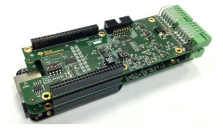
The 8-Channel 1A/Ch High Side Driver for Programmable Logic Controller Reference Design (TIDA-00183) can record output currents and compare them in real time with a stored reference. Each of the 1A outputs has a function to measure the output current. Every type of load has a specific current pattern when switched on. A classic light bulb, for example, starts with a current 10 times as high as its average current during operation. A relay begins with a soft current, which then increases to its operational level. A motor starts with a high current peak but then settles to a level corresponding to its mechanical loading.
How can the manufacturer apply this current recording function to protect the machine and also conduct some forensics when damage happened? The controlling PLC knows when it turns on and off a load. The machine’s designer knows what type of load is connected to which output. These two pieces of information, together with current sensing, enable the PLC to verify the connected loads in real time. Alternatively the machine could record the current patterns of all connected loads during the end test of the machine before shipment and store the patterns for later reference and verification. This verification not only makes unauthorized modifications visible, but also the effects of aging and defective loads. In many cases, the machine can then inform the operator early enough that the machine will break or has been modified by unauthorized personnel.
The current-sensing feature demonstrated in TIDA-00183 can even do more. It enables the implementation of soft fuses, which are software-configurable protection schemes specifically tailored to the connected load. Also load balancing could be realized; if one output needs more current than the output quota of 1A but a couple of others need less, the PLC can adjust the current limits accordingly as long as the sum of currents stays under the module limit. These functions help achieve a level of functionality and diagnostics that simply haven’t existed before.
Additional Resources
- Find more information about end-equipment solutions for PLCs.
- Check out TI's factory automation overview for reference designs and product solutions.