SSZTC12 october 2015 FDC1004 , FDC2112 , FDC2114 , FDC2212 , FDC2214
Capacitive sensing can present itself in many applications, ranging from proximity detection and gesture recognition to liquid-level sensing. Regardless of application, the defining factor of capacitive sensing is the ability to sense a change in sensor capacitance from a certain baseline. Depending on the specific application and system requirements, you may need different ways to measure this change.
In this post, I will cover two specific types of architectures – the switched-capacitor circuit and inductor-capacitor LC tank circuit – currently being used in capacitive sensing.
The Switched-capacitor Circuit
Figure 1 shows a simplified circuit for capacitive sensing based on charge transfer, where switches implement the sample-and-hold operation. The change in charge on the sensor capacitor between samples causes a changing output voltage, which then becomes the quantity you measure to determine the change in capacitance.
 Figure 1 Schematic of a Simplified
Switched-capacitor Circuit with Sample-and-hold Operation
Figure 1 Schematic of a Simplified
Switched-capacitor Circuit with Sample-and-hold OperationTo sample the charge on the sensor, the sensor capacitor, CS, is charged up by closing switch S1 and opening switches S2 and S3. Once CS has charged up, S1 and S3 will open while S2 closes. This allows the accumulated charge on the sensor capacitor to be directly transferred to the holding capacitor, CH. Once CH is charged up, S1 and S2 will open while S3 closes. This forces isolation between the discharging of the sensor capacitor (to prepare for the next sample) and the buffering of the output-voltage potential (held steady by CH).
This is a widely popular architecture used for capacitive sensing because its sampling state and holding state are all decoupled due to the operation by switches. There are some disadvantages with this technique, however, in that it is more susceptible to noise. Because the sensor has wideband characteristics, noise from external interferences – even at frequencies different from the operating frequency – can still present issues. You may need external circuitry for filters, which would increase system complexity and possibly reduce the sensitivity if the filters introduce significant parasitic capacitance. However, if the system is not exposed to wideband noise, this architecture may suffice.
The LC Tank Circuit
The LC resonator shown in Figure 2 is another sensor architecture used in capacitive sensing. Equation 1 determines the oscillation frequency of the LC tank.
 Figure 2 Schematic of a Simple LC
Tank
Figure 2 Schematic of a Simple LC
Tank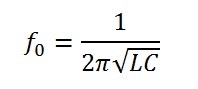
Looking at Equation 1, it is clear that the oscillation frequency depends only on the total inductance and total capacitance of the tank. Therefore, given that the intent of capacitive sensing is to measure a change in capacitance, the total inductance of the tank is fixed and the capacitive component of the resonator forms the sensor. As the capacitance changes due to the sensor’s response to targets, the oscillation frequency will shift. The change in tank frequency then becomes the quantity that you measure to determine the measured change in capacitance.
Although the architecture of the LC tank is fairly simple, there are a couple of major advantages with this circuit that make it a relatively novel approach to capacitive sensing. First, due to its inherent narrowband characteristics (shown in Figure 3), an LC resonator provides excellent immunity to electromagnetic interference (EMI). Also, if there are any known frequencies at which noise sources do exist, it is possible to filter out these noise sources without the use of external filters by shifting the operating frequency of the sensor. This will help increase the sensitivity of the system (if the application requires high sensitivity) and reduce its complexity.
However, these sensors are more complicated to design with than a traditional switch-capacitor circuit. For uni-directional sensing, we recommend the FDC1004 due to its integrated active shield drivers.
 Figure 3 LC Resonator Characteristic
Curve
Figure 3 LC Resonator Characteristic
CurveTI's Portfolio
TI carries both types of architectures in its portfolio. The FDC1004 is TI’s version of the switched-capacitor architecture, and the FDC221x is TI’s version of the LC tank architecture.
To jumpstart development on these architectures, explore TI Designs reference designs:
- Backlight and smart lighting control by ambient light and proximity sensor reference design, based on the FDC1004.
- Capacitive-based liquid level sensing sensor reference design, based on the FDC1004.
- Noise-immune capacitive proximity sensor system reference design, based on the FDC2214 for proximity sensing applications requiring higher sensitivity.
Additional Resources
- Learn about TI’s new FDC2214 capacitive-sensing family.
- Find out more about capacitive sensing in the capacitive sensing infographic.
- Watch the capacitive sensing overview video.
- Read other blog posts about capacitive sensing.
- Interact with other engineers on the TI E2E™ Community Capacitive Sensing forum.
- Explore TI’s sensing portfolio.