SSZTC46 september 2015
Recently, my colleagues have discussed various digital interface options for motor position encoders, including the EnDat and BiSS interfaces. The High-Performance Interface Digital Servo Link (HIPERFACE DSL) digital protocol completes the panorama of possible digital interfaces to motor position encoders.
The robustness of this protocol enables connections to a motor-feedback system through a motor connection cable and simplifies the installation of an encoder system in a motor drive. SICK, a German company that sells sensors, owns and specifies the HIPERFACE DSL® digital protocol.
Some of the main advantages of HIPERFACE DSL are based on the opportunity for connection of the encoder:
- A digital interface on the frequency inverter for all communication with the motor feedback system. The interface complies with the RS-485 standard with a transfer rate of 9.375 MBaud.
- Communication with the encoder via a twisted pair cable.
- Power supply and communication with the encoder can be carried out using the same twisted pair cable. This is possible by the enhancement of the frequency inverter with a transformer.
- The connection cables to the encoder can be routed as a shielded, twisted-pair cable in the power supply cable to the motor. This means that no encoder plug connector to the motor and to the frequency inverter is necessary.
- The cable length between the frequency inverter and the motor feedback system can be up to 100 m, without degradation of the operating performance.
Encoder Interface Circuit
You can use the HIPERFACE DSL protocol in two different interface circuit configurations, each with a different kind of connection cable:
- A four-wire
interface/separate encoder cable (i.e., power separated from data). See Figure 1.
 Figure 1 Four-wire Interface
Circuit with Separate Encoder Cable
Figure 1 Four-wire Interface
Circuit with Separate Encoder CableThe HIPERFACE DSL specification provides the corresponding values of the passive components for line termination: R1 = R2 = 56Ω, R3 = 10kΩ, C1 = 100nF and C2 = 2.2µF.
- A two-wire
interface/integrated motor cable (see Figure 2). When using a two-wire cable integrated in the motor cable
(where communication occurs over the supply lines), you will need a transformer
to increase the common-mode rejection ratio. The supply voltage and GND are
coupled onto the RS-485 differential signals through inductors L1 and L2, and
DC-decoupled to the transformer through capacitors C3 and C4. The differential
RS-485 signals after the transformer are AC-coupled to the supply lines through
properly designed LC filters.
 Figure 2 Two-wire Interface
Circuit with Integrated Motor Cable
Figure 2 Two-wire Interface
Circuit with Integrated Motor CableThe HIPERFACE DSL specification provides the corresponding values of the passive components for line termination: R1 = R2 = 56Ω, R3 = 10kΩ, C1=100nF, C2 = 2.2µF/16V, C3 = C4 = 470nF/50V and L1 = L2 = 100µH.
A Solution for the HIPERFACE DSL Encoder Interface
The Two-Wire Interface to a HIPERFACE DSL Encoder TI Designs reference design implements an industrial temperature and EMC-compliant two-wire interface to a HIPERFACE DSL position encoder. Like EnDat and BiSS interfaces, HIPERFACE DSL is used in most major industrial/motor drive applications, since it interfaces to motor position encoders.
The major building blocks of this reference design are a two-wire bidirectional RS-485 physical interface with power over RS-485 and a HIPERFACE DSL-compliant encoder power supply with overvoltage, over-current and short-circuit protection.
Figure 3 is a simplified system block of a servo drive with a master interface to a HIPERFACE DSL encoder.
 Figure 3 TIDA-00177 TI Designs Reference Design
System Overview
Figure 3 TIDA-00177 TI Designs Reference Design
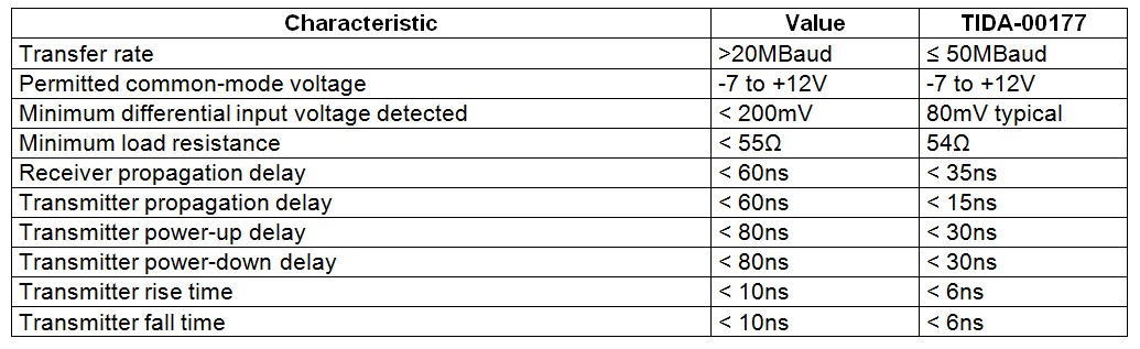
System OverviewTable 1 and 2 summarize HIPERFACE DSL specifications versus the TI Designs reference design. Table 1 describes the Physical Layer of the RS-485 interface, while Table 2 describes the power supply requirements.
HIPERFACE DSL Physical Layer
As a physical layer, HIPERFACE DSL uses a transfer in accordance with EIA-485 (RS-485). Valid RS-485 interface transceiver must comply with the constraints listed in Table 1.
|
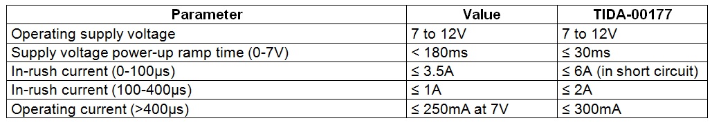
HIPERFACE DSL Encoder Supply Voltage
Table 2 lists the specifications for the HIPERFACE DSL power supply.
The HIPERFACE DSL interface completes and closes the overview of the digital interfaces to motor position encoders.
In the next installment of this series, my colleagues and I will take a closer look at the interface to sin/cos encoders for high-resolution position interpolation.
If you would like to see this series touch on specific topics related to position encoder interface design, please post a comment below.
Additional Resources:
- For details on this protocol, see the HIPERFACE DSL protocol specifications.
- Visit SICK’s website for more about the HIPERFACE DSL master IP core.
- Learn more about TIDA-00177 reference design or watch this informational video.
- Read other blogs on designing industrial, EMC-compliant interfaces to motor position encoders.