SSZTC78 september 2015 LMT70 , TMP117
Technological advancements have allowed temperature sensor integrated circuits (ICs) to be used for precision applications such as human body temperature measurement found in wearable health bands and medical devices. TI’s temperature sensing team has received many questions regarding these types of applications with the recent release of the accurate, small-form-factor LMT70 analog temperature sensor for human body temperature measurement. As I have answered some of these questions in the past with other sensors, I thought I would cover a few in this post
Q: When monitoring a sensor with an analog-to-digital converter (ADC), how can you achieve better quantization error with a 12-bit ADC, such as the one found in MSP430™ ultra-low-power microcontrollers (MCUs)?
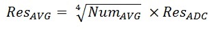
A: Using rolling averages in the software can improve the resolution of the ADC – you can actually change the number of averages and see that the noise level as well as the resolution increase or decrease. Rolling averaging works if the noise amplitude of the signal applied to the ADC input is greater than the ADC’s least significant bit (LSB). For example, using a rolling average of 16 samples extends 12-bit ADC resolution to 14 bits using Equation Equation 1:
The LMT70 evaluation module uses the MSP430 MCU’s 12-bit ADC. The typical performance of this evaluation module has shown to be ±0.07°C due to this technique.
Q: How does the transfer function affect the overall accuracy of the analog temperature sensor?
A: There are accuracy curves in many data sheets that show how different equations affect accuracy. Regarding the LMT70, with second- or third-order curves, the accuracy is about the same as the lookup table (LUT) for the limited temperature range of human body temperature measurement, so the device will meet the same specifications. Of course, as the curves show in Figure 1 and Figure 2, the third-order equation given in the data sheet for 10°C to 110°C is best to use. Even a second-order curve that is best fit for 20°C to 45°C may give acceptable results.
How do you generate this equation? Use Excel or MATLAB curve fitting. And how do you generate the accuracy curves? Simply plug in the minimum and maximum voltage limits found in the data sheet’s electrical characteristic (EC) table into your equation.
 Figure 1 Using a Third-order
Transfer-function Best Fit, 10oC to +110oC
Figure 1 Using a Third-order
Transfer-function Best Fit, 10oC to +110oC Figure 2 Using a Second-order Transfer
Function Best Fit, 10oC to +110oC
Figure 2 Using a Second-order Transfer
Function Best Fit, 10oC to +110oCQ: Can a battery that varies from 1.8V to 3V directly power an analog sensor, and what is the impact on accuracy?
A: Analog sensor data sheet specifications include power-supply sensitivity as well as curves so that you can determine the impact on accuracy. Let’s look at the LMT70 as an example. Figure 3 (from page 9 of the LMT70 data sheet) shows a typical curve found in analog temperature sensor data sheets.
 Figure 3 LMT70 Line Regulation
As you can see, accuracy down to 2V is very good for a typical LMT70 sensor. Each division in this curve is 0.5mV, so that is 0.1°C. The power-supply sensitivity limit is +/-9m°C/V. Thus for a range of 2V to 3V, you get a variation of no more than 0.009°C. For a target of 0.1°C-0.2°C, the impact on error is negligible.
All ICs have a voltage level where they start to malfunction or turn off. For the LMT70, this occurs below 2V, as listed on the EC table. If you try a few LMT70 sensors on the bench, you may find that some work below 2V, but TI does not specify the IC for that voltage. IC manufacturers do extensive characterization on devices to ensure that datasheet specifications cover future production variations.
Q: Electrostatic discharge ESD – Do I need to be worried about it?
A: If you are worried about the ESD at connectors and those connectors will be user-accessible, you need to protect both the MCU board and the IC sensor, as shown in Figure 4 in red. You could also add notes in the user’s guide warning about using ESD safe practices when handling the boards/assemblies.
 Figure 4 Sensor Placed off
Board
Figure 4 Sensor Placed off
BoardIf users won’t be able to access the connector, the analog temperature sensor should be handled in an ESD-safe environment. For the LMT70 specifically, no additional ESD protection is necessary, as this sensor has built-in ESD protection for manufacturing purposes.
Please leave us a note below and let us know what else you would like to know about IC temperature sensors—perhaps we’ll answer them in a future blog post!
Additional Resources
- Learn more in this blog about design considerations for a wearable temperature monitoring system, using the TMP117M, TI’s ultra-high-accuracy ±0.1°C temperature sensor for medical applications.
- Download the LMT70 data sheet.
- Read TI’s application note, “Wearable Temperature Sensing Layout Considerations Optimized for Thermal Response.”
- Visit the LMT70 technical documents page for other application notes.
- Find out more about TI’s temperature sensors.