SSZTCM3 june 2015 TDC1000 , TDC7200
Flow meter manufacturers are responding to the needs of utility companies by rapidly adopting advanced ultrasonic flow measurement technology. Like most companies, utilities generally are in business to generate revenue from the service they provide, and they are keen to drive revenue without simply increasing rates. One of the best ways to do this is to more accurately monitor their customers’ usage of water and gas.
The majority of traditional utility meters are mechanical: inside the meter, there’s a mechanical wheel that measures water and gas usage by counting the number of times the wheel completes a full revolution. This sounds simple, but it’s not difficult to identify some flaws. The mechanical wheel spins most effortlessly when it is originally placed in the field. From that point forward, build-up of contaminants from the water and gas on the moving components will slow wheel rotation, which will shorten the operating life and degrade accuracy. In short, the degrading accuracy of a mechanical meter causes the utility company to lose money.
How Ultrasonic Flow Meters Work
Unlike mechanical meters, ultrasonic flow meters have no moving parts. There is nothing to break down or degrade performance over time. In addition to being robust, ultrasonic meters are extremely accurate at measuring low flow rates, which means that utility companies can get paid for every drop of water and puff of gas that their customers use. Plus, they are virtually tamperproof.
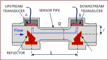
Figure 1 shows the inner components of an ultrasonic flow meter. The flow sensor consists of a pipe with a nominal diameter, D, and two piezoelectric transducers placed at fixed distance, L, from each other. The transducers are mounted in a protective housing. The housing and the transducers are inserted into holes in the pipe, exposing the inner covers of the transducers to the fluid in the pipe. Two acoustic reflectors in the pipe direct the ultrasonic signals from one transducer to the other.
 Figure 1 Ultrasonic Sensor Cell
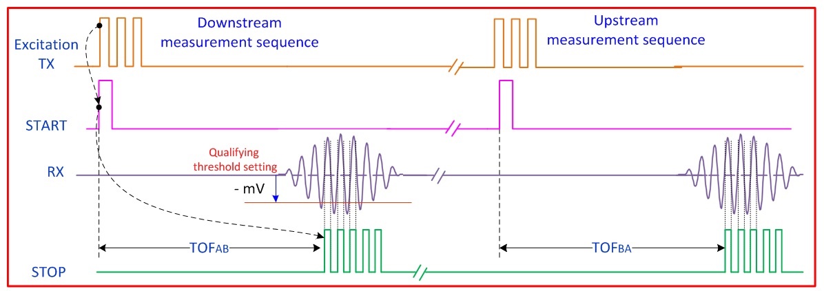
The technique of measuring flow with ultrasonic sensing is called delta time of flight (TOF). A measurement sequence begins by applying a burst of pulses to transducer A. Transducer A generates ultrasonic-pressure pulses that are directed toward transducer B through the acoustic reflectors in the pipe. As shown in Figure 2, when the first pulse is applied to transducer A, a start signal marks the beginning of the TOF measurement. On the receiver side, transducer B and the related signal processing electronics detect the incoming wave and generate a stop pulse to mark the time when an ultrasonic pulse is received. The time taken for the ultrasound wave to travel from A to B (the time between the start and the first stop pulse) is the TOF.
 Figure 2 Upstream and Downstream Transmit-receive Sequence for Measurement of Difference in TOF
A precision timer measures the TOF from transducer A to B (TOFAB). After receiving the signal, transducer B switches to transmitting a set of ultrasonic-pressure pulses, which are then received by transducer A, thus creating a TOF measurement from B to A (TOFBA). The difference, or delta, between TOFAB and TOFBA is proportional to the velocity of the flow of the water or gas in the pipe.
These measurements can be accurate to within picoseconds with ultrasonic flow meters based on sensing products like TI’s TDC1000 ultrasonic analog front-end and TDC7200 time-to-digital converter. That’s why utility companies are making the switch to ultrasound.
Additional Resources
- Learn more about ultrasonic sensing.
- Check out the TI Design ultrasonic flow meter reference design.
- Read the water flow and heat meters application note.