SSZTCP3 may 2015 UCD3138 , UCD3138A , UCD7138
OK. I know the title is really corny, but I think you’re really going to like this post if you give it a chance.
We’ve all heard over and over about the great things intelligent power will bring to the power-supply industry. In many ways it has met or exceeded our expectations; however, in other ways it has also let us down. I can’t help but think that some of this stems from the fact that it’s easy to get enamored with cool technology just because it’s different or new; we overlook the fact that it has not done something truly great. In other words, some of us may feel that intelligent power is awesome, but we are not sure what we’re going to do with it that demonstrates its awesomeness.
I want to go over a new technology enabled by the intelligence of digital power. I think you will find it both awesome and incredibly useful. Essentially, this is a new synchronous rectification scheme that increases the efficiency, robustness and design ease of an LLC converter.
Now hold on. Before your eyes roll back in your head and you doze off, keep listening. The cool factor is coming. I promise!
In order to appreciate this technology, let’s review of some of the challenges associated with the design of a robust synchronous rectification solution for an LLC converter. At its simplest level, synchronous rectification requires that a MOSFET emulate the behavior of a diode. Simply put, when current wants to flow from anode to cathode, the MOSFET turns on. As soon as it begins to flow from cathode to anode, the MOSFET turns off.
Pretty simple, right? But the devil is in the details.
For example, if the MOSFET turns off too early, the resulting current flows through the MOSFET body diode. If this happens too much, efficiency will suffer, and we all know that we need efficiency to be as high as possible. (If there’s any doubt about this, just ask the Environmental Protection Agency. If the MOSFET is on too long, not only will efficiency go down, but the resulting current flow can actually destroy the MOSFET. So the trick is to determine the optimal time to turn off the MOSFET such that the body diode doesn’t conduct any longer than necessary – and yet still make sure that the MOSFET isn’t subjected to excessive voltages.
Figure 1 illustrates a solution to this problem. In addition to turning the MOSFET on and off, the driver also sends a digital message to the controller on a cycle-by-cycle basis. This message precisely tells the controller how long the body diodes of SR1 and SR2 are conducting. The controller uses this information to calculate a new pulse width that will either increase or decrease the body-diode conduction time. This is analogous to having an engineer monitor every pulse applied to the MOSFET to see if it used a pulse width that is too long or too short.
 Figure 1 UCD3138A & UCD7138 LLC
Synchronous Rectifier Solution
Figure 1 UCD3138A & UCD7138 LLC
Synchronous Rectifier SolutionNow if that isn’t cool enough, the controller doesn’t just use this information to optimize efficiency; it also uses it to improve system robustness. Highly efficient synchronous rectification demands that the body-diode conduction time be as short as possible. Remember that too little time can be dangerous. So the digital controller acts like a watchdog, constantly on the lookout for any gate-drive pulses that result in too short of a body-diode conduction time. If it sees one of these events, it immediately corrects it on the next cycle.
We’ve seen all sorts of efficiency improvements from this technology. Figure 2 shows one example where average efficiency increased by over 0.6%.
 Figure 2 UCD3138A & UCD7138
Efficiency Improvement
Figure 2 UCD3138A & UCD7138
Efficiency ImprovementI had promised to show you just how
cool this technology can be. Remember the expression, “a picture is worth a thousand
words?” Take a look at Figure 3 to see how dramatic the performance enhancements of
this technology are. Figures 3A and 3B show how the technology can protect the
system from excessively long gate-drive pulses. Notice the huge voltage spikes on
the MOSFET VDS in the image at left. When the optimization technology is
turned on, the gate-drive pulse is shortened and the result resembles something like
you would see in a textbook. 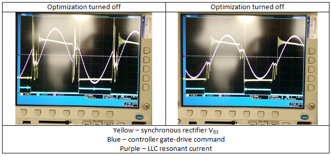
Find out more information about this technology at: