SWRA705 August 2021 AWR1243 , AWR1443 , AWR1642 , AWR1843 , AWR1843AOP , AWR2243 , AWR2944 , AWR6443 , AWR6843 , AWR6843AOP , AWRL1432 , AWRL6432 , IWR1443 , IWR1642 , IWR1843 , IWR2243 , IWR6243 , IWR6443 , IWR6843 , IWR6843AOP , IWRL6432 , IWRL6432AOP
4.1 Rectangular Radome Angle Dependent Error
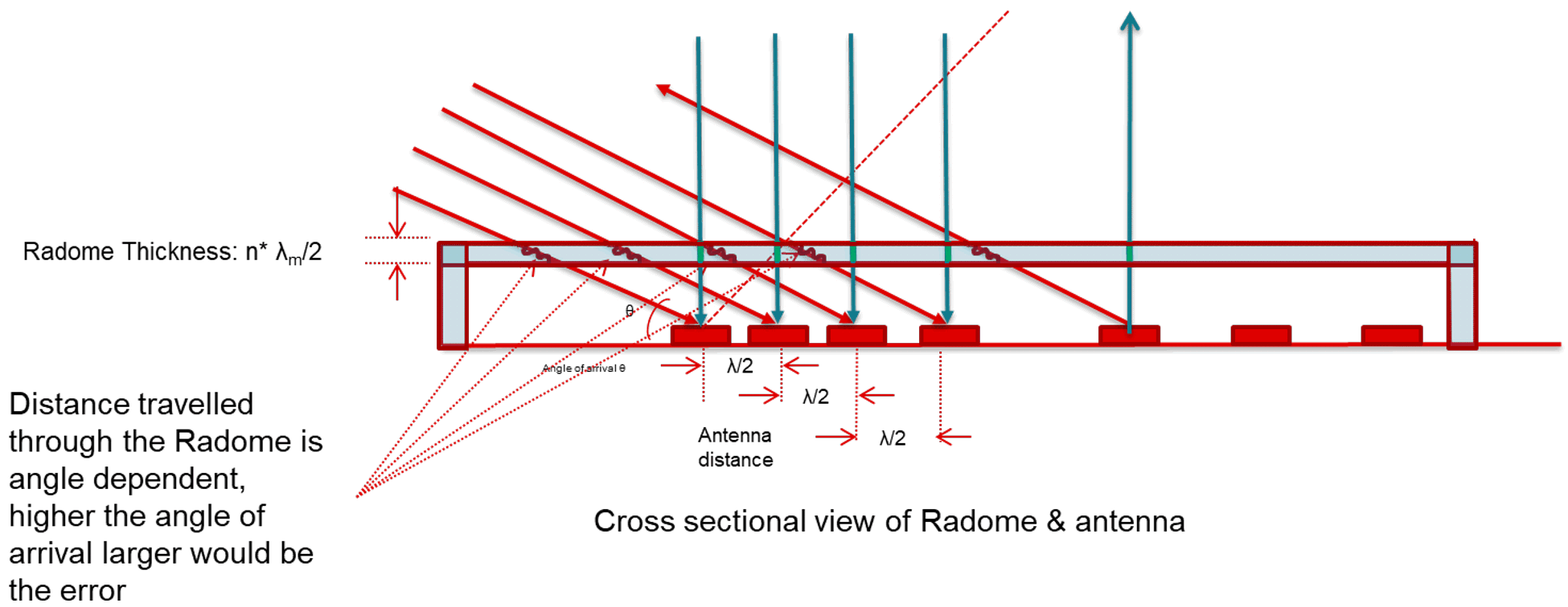
Electrical distance traveled through the radome in boresight is equivalent to the thickness of the radome wall. However, this distance increases as angle of arrival increases and results in a higher angle estimation error. This effect is shown in Figure 4-1.
The theory behind this phenomenon is such that if the radome wall thickness is designed to be λ/2 (half wavelength), then the round trip of the radar signal passing through the inner wall surface, then reflected back from the outer wall surface introduces a net 180° phase shift (180° -180° + 180°) emitted from the inner wall.
Therefore, at boresight of the rectangular radome, the reflections at the inner wall will cancel since they are out of phase, resulting in low net reflections. However, when moving away from the boresight to higher grazing angles of arrival, the distance traveled by the mmWave signal is greater than “optimal thickness” or “half-wavelength”. This causes multiple reflections at the radome interface boundary resulting in ripples in the antenna radiation patterns and leading to nulls. These ripples and nulls can cause inconsistency in the detection of the objects at higher grazing angles resulting in angle estimation errors. This effect can be counteracted by tapering the radome wall towards the extents of the radar FoV, however, this will also compromise the strength of the radome.
 Figure 4-1 Distance Traveled in
Rectangular Radome Wall for Different Grazing Angles