TIDUDO6B May 2019 – October 2020
- Description
- Resources
- Features
- Applications
- 5
- 1System Description
-
2System Overview
- 2.1 Block Diagram
- 2.2 Highlighted Products
- 2.3
System Design Theory and Design Considerations
- 2.3.1 AFE4900 and Power Supply
- 2.3.2 CC2640R2F Microcontroller
- 2.3.3 PPG Measurement
- 2.3.4 ECG Measurement
- 2.3.5 Selecting TX Supply (TX_SUP) Value for Driving LEDs
- 2.3.6 Generating TX Supply for Driving LEDs
- 2.3.7 Generating RX Supply for AFE4900
- 2.3.8 Generating I/O Supply
- 2.3.9 Battery Input and Reservoir Capacitors
- 2.3.10 Battery Life Calculations
- 2.3.11 External Memory
- 2.3.12 LED Indications
- 2.3.13 Connections Between Sensor Board and ECG Board
-
3Hardware, Software, Testing Requirements, and Test Results
- 3.1 Required Hardware and Software
- 3.2 Testing and Results
-
4Design Files
- 4.1 Schematics
- 4.2 Bill of Materials
- 4.3
PCB Layout Recommendations
- 4.3.1 Layout for Main Board
- 4.3.2 Connection From PDs to AFE
- 4.3.3 Connections From LEDs to AFE
- 4.3.4 Connections From ECG PADs to AFE
- 4.3.5 Connections Between BT and AFE
- 4.3.6 Connections Between BT Antenna and Chip
- 4.3.7 Boost Converter
- 4.3.8 Buck-Boost Converter
- 4.3.9 Layouts for PPG Sensor Boards
- 4.3.10 Layout for ECG Sensor Board
- 4.3.11 Layout Prints
- 4.4 Altium Project
- 4.5 Gerber Files
- 4.6 Assembly Drawings
- 5Software Files
- 6Related Documentation
- 7About the Authors
- Revision History
3.2.2.3 PTT Measurement
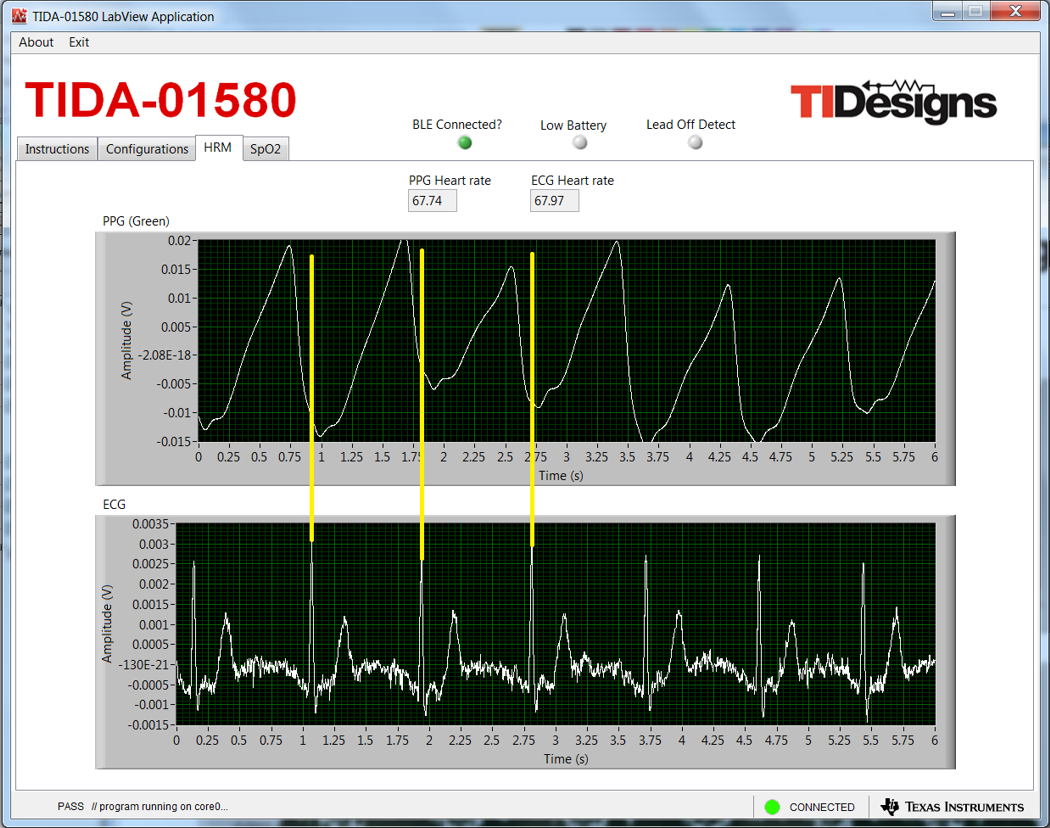
Figure 3-28 shows the PTT measurement.
 Figure 3-28 Measurement Showing Constant PTT
During testing, it was observed that the power line noise and other motion artifacts getting coupled to the PPG signals drastically reduced the SNR. For HRM applications, it is imperative to remove the noise and baseline drift. Heart-rate estimation usually requires an algorithm that filters the noise and detects the beat-to-beat heart rate and average heart rate. Even under rest conditions, extraction of heart rate data can get complicated, due to sudden changes in the DC level of the signal, due to respiration and motion artifacts. The heart rate can be calculated by measuring the separation between the successive peaks of the signal after eliminating the effect of the sudden DC-level shifts. In the presence of artifacts such as motion, the PPG signal can be buried. This occurrence requires motion cancellation algorithms, usually aided by data from accelerometers, to be able to remove the motion artifact and extract the heart rate.