DLPU103B october 2020 – may 2023 DLP230NP
- 1
- DLP LightCrafter Display 230NP EVM
- Trademarks
- 1 DLP LightCrafter Display 230NP EVM Overview
- 2 Safety Instructions
- 3 Applicable Documents
- 4 What is in the DLP LightCrafter Display 230NP EVM?
- 5 Light Engine
- 6 Quick-Start Procedure
- 7 Connectors on Formatter Board
- 8 EVM Setup
- 9 Raspberry Pi Guide
- 10Troubleshooting
- 11Support Resources
- 12Revision History
8 EVM Setup
The DLP LightCrafter Display 230NP EVM is composed of two main parts:
- DLPDLCR230NPEVM formatter board
- Engine with LED connection, flex cable, and mechanical setup
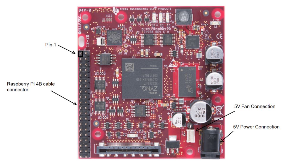
The formatter board contains the connector for the power supply, the connector for the fan, and the Raspberry PI ribbon cable connector. It also contains a protection circuit which prevents the power up of the DLP chipset when no fan is connected to the board. This also applies if the connection is loose or in case a fan wire is broken. Figure 8-1 shows the DLPDLCR230NPEVM formatter board with the main connections:
 Figure 8-1 DLP®LightCrafter™
230NP EVM Formatter Board
Figure 8-1 DLP®LightCrafter™
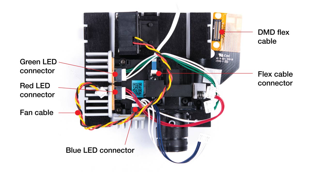
230NP EVM Formatter BoardThe light engines contain the LED connectors and the flex cable which connects to the formatter board on the bottom via J500. Figure 8-2 shows the optical engine connections.
 Figure 8-2 DLPDLCR230NPEVM Optical Engine
Connection
Figure 8-2 DLPDLCR230NPEVM Optical Engine
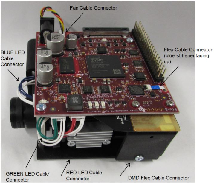
ConnectionThe DLPDLCR230NPEVM formatter board is mounted on top of the mechanical base. The fan cable has to be connected all the way to ensure proper connection of the fan wires to the PCB. Figure 8-3 shows the formatter board mounted on the mechanical assembly with all cables connected.
 Figure 8-3 DLP®LightCrafter™ Display 230NPEVM
Ensure a good connection of the flex cable, fan and LED cables to the DLP LightCrafter Display 230NPEVM formatter board before turning it on.