SBAA203B may 2013 – april 2023 REF5010 , REF5020 , REF5025 , REF5030 , REF5040 , REF5045 , REF5050
1 Description
One of the authors is working in a Mars-Energo high-voltage measurement laboratory, which has a high need for precision voltage sources (such as 1000 V, 5000 V, and 10000 V). One method to build these kinds of voltage sources is to use serially-connected Zener diodes. However, Zener diodes have low precision and stability. The REF50xx reference sources have high stability, but in the official data sheet there is no recommendation on how to connect devices serially.
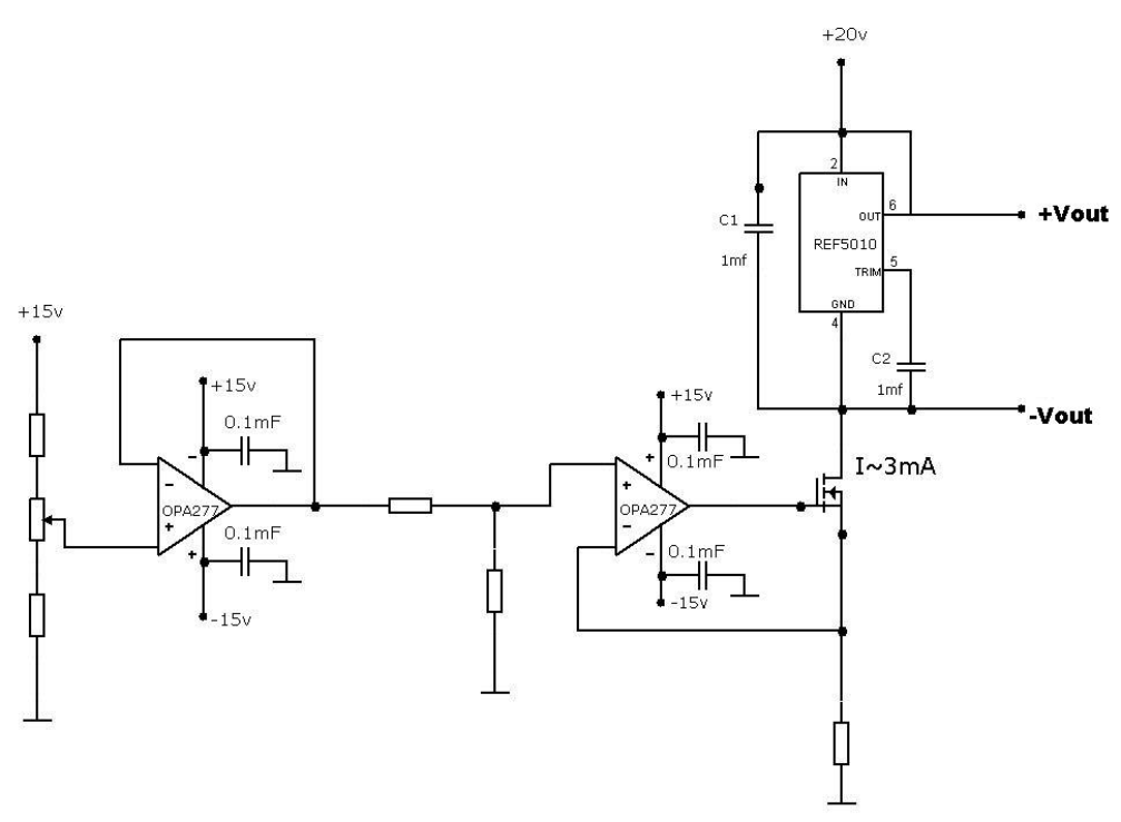
The precision and stability characteristics of the REF5010 are so intriguing that they have forced the authors to perform some experimentation. As a result, it was discovered that by connecting the Vin and Vout pins together, the REF50xx is converted to an ideal Zener diode without any negative side effects, as shown in the schematic of Figure 1-1.
 Figure 1-1 REF5010 in Zener Diode Mode
There is only one data sheet operating condition violation in Figure 1-1. REF50xx performance is only ensured when Vin is at least 200 mV greater than the +Vout voltage. The REF50xx ground pin current is set in Figure 1-1 to 3 mA, where 0.8 mA (according the data sheet) is the device quiescent current and 2.2 mA is the +Vout pin sinking current. Likewise, the Vout pin has an input current that is stabilized within the ±10 mA specified +Iout range. Experiments made with this schematic demonstrated that if a device ground pin current is within the range of 3 mA to 8 mA, the voltage difference between the +Vout and –Vout pins is very precise and stable. However, a significant difference between the standard device application and Figure 1-1 is that in Figure 1-1 there is a two-terminal precision device, which can be easily connected serially (see Figure 1-2).
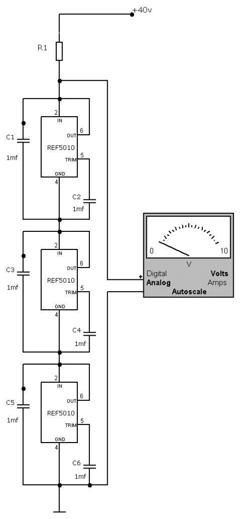
 Figure 1-2 REF5010 Connected Serially as Usual Zener Diodes
Experiments performed with the schematic of Figure 1-2 demonstrated the same results as the experiments from Figure 1-1. If the current regulated by R1 stays within the range of 3 mA to 8 mA, the output voltage remains stable and is equal to three times the specified voltage of the REF5010 data sheet. The same results are confirmed with other REF50xx device family members.
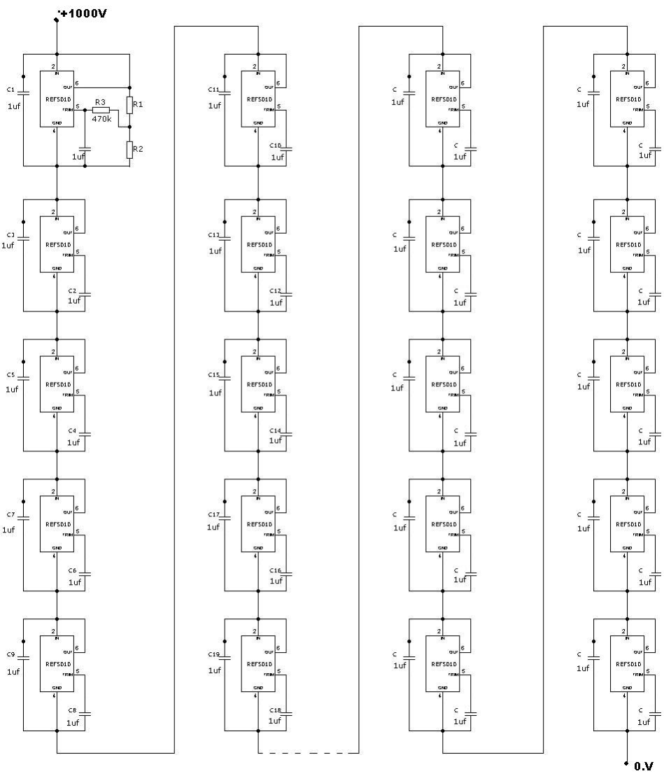
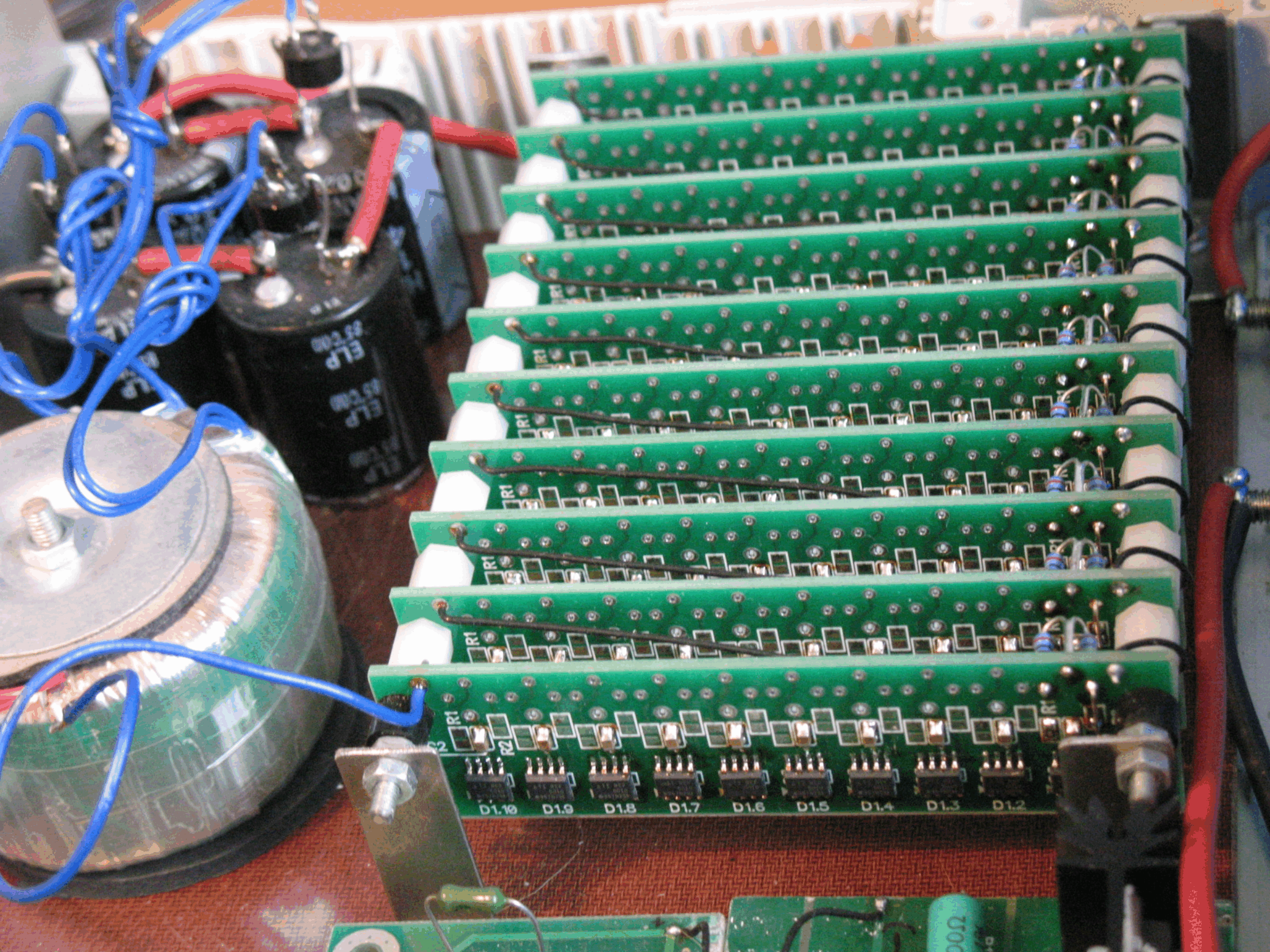
The precision 1000-V reference voltage source is designed by serially connecting 100 REF5010 devices. Each REF5010 is configured as a two-terminal device. Together, the devices create a 1000-V precision reference source. The top left REF5010 device functions as a voltage adjuster that allows the targeted 1000-V to be set more precisely. However, there is little need for fine tuning because the 100-part averaged value is very close to the ideal 10 V despite some part-to-part variation. The small range of adjustment needed only confirms the statement that if normal distribution is present, a precision device can be built without using precision components. Refer to Figure 1-3. Figure 1-4 illustrates the interior view of the 1000-V voltage source.

