SBOA442 March 2021 TMP107 , TMP107-Q1
1 Introduction
The SMAART wire bus interface communicates over a single wire using a half-duplex UART (Universal Asynchronous Receiver Transmitter) interface. The half-duplex communication requires careful timing and mechanisms that prevent collisions on the bus. The auto-baud detection feature ensures that the temperature sensor always replies at the same communication speed (baud rate).
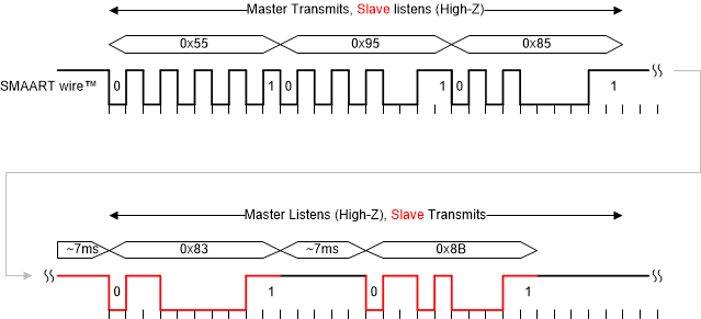
Figure 1-1 shows a snippet of the communication for the Address initialize command. The temperature sensor listens to the bus by default. Its input pin I/O is high impedance. The master device always initiates the communication first. The temperature sensor uses the first calibration byte 0x55 for baud rate detection. The second byte 0x95 corresponds to the Address initialize command. The third byte 0x85 assigns the first device address to 8. Then, the master device releases the bus and waits for the reply from the sensor. Each temperature sensor on the SMAART wire bus interface replies with the assigned 5-bit address (bytes 0x83, 0x8B). See the Communication Protocol section in the TMP107-Q1 Automotive Grade, ±0.4°C Temperature Sensor with Daisy-Chain UART, EEPROM, and Alert Function Data Sheet, for details.
 Figure 1-1 TMP107 Communication
Example - Identify Command
Figure 1-1 TMP107 Communication
Example - Identify CommandFigure 1-2 shows an example of interfacing the TMP107-Q1 temperature sensor. The TXD signal drives the enable pin of the buffer instead of driving the input. This implementation converts the push-pull output to open drain (open collector). The 4.7-kΩ pullup resistor brings the bus to logic 1 during standby. The SMAART wire bus interface transfers data reliably up to 300 meters. This also means that the parasitic inductance of the signal wire and mismatched impedance may cause ringing and overshoots. The 100-Ω resistor protects the RXD input from damage by reducing the current through the integrated ESD protection diodes during transient events below GND and above VCC rail. The 10-Ω resistor eases signal collisions and slows down signal edges. This improves signal integrity.
 Figure 1-2 TMP107 SMAART wire™ Interface