SBOS207C October   2001  – December 2015 PGA2310

PRODUCTION DATA.  

  1. Features
  2. Applications
  3. Description
  4. Revision History
  5. Pin Configuration and Functions
  6. Specifications
    1. 6.1 Absolute Maximum Ratings
    2. 6.2 ESD Ratings
    3. 6.3 Recommended Operating Conditions
    4. 6.4 Thermal Information
    5. 6.5 Electrical Characteristics
    6. 6.6 Typical Characteristics
  7. Detailed Description
    1. 7.1 Overview
    2. 7.2 Functional Block Diagram
    3. 7.3 Feature Description
      1. 7.3.1 Analog Inputs and Outputs
      2. 7.3.2 Serial Control Port
      3. 7.3.3 Gain Settings
      4. 7.3.4 Daisy-Chaining Multiple PGA2310 Devices
      5. 7.3.5 Zero Crossing Detection
      6. 7.3.6 Mute Function
    4. 7.4 Device Functional Modes
      1. 7.4.1 Power-Up State
  8. Application and Implementation
    1. 8.1 Application Information
    2. 8.2 Typical Application
      1. 8.2.1 Design Requirements
      2. 8.2.2 Detailed Design Procedure
      3. 8.2.3 Application Curve
  9. Power Supply Recommendations
  10. 10Layout
    1. 10.1 Layout Guidelines
    2. 10.2 Layout Example
  11. 11Device and Documentation Support
    1. 11.1 Device Support
      1. 11.1.1 Development Support
    2. 11.2 Documentation Support
      1. 11.2.1 Related Documentation
    3. 11.3 Community Resources
    4. 11.4 Trademarks
    5. 11.5 Electrostatic Discharge Caution
    6. 11.6 Glossary
  12. 12Mechanical, Packaging, and Orderable Information

5 Pin Configuration and Functions

D and P Pakcages
16 Pins SOIC and PDIP
Top View
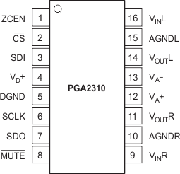
PGA2310 sbos207_po.gif

Pin Functions

PIN I/O DESCRIPTION
NO. NAME
1 ZCEN I Zero Crossing Enable Input (Active High)
2 CS I Chip Select Input (Active Low)
3 SDI I Serial Data Input
4 VD+ I Digital Power Supply, 5 V
5 DGND Digital Ground
6 SCLK I Serial Clock Input
7 SDO O Serial Data Output
8 MUTE I Mute Control Input (Active Low)
9 VINR I Analog Input, Right Channel
10 AGNDR Analog Ground, Right Channel
11 VOUTR O Analog Output, Right Channel
12 VA+ I Analog Power Supply, 15 V
13 VA I Analog Power Supply, –15 V
14 VOUTL O Analog Output, Left Channel
15 AGNDL Analog Ground, Left Channel
16 VINL I Analog Input, Left Channel