SBOU157 September 2015 OPT8241
- Voxel Viewer
4.1 Lens Calibration
Lens calibration aims at overcoming optical distortions introduced by the lens. In absence of any optical distortions, each pixel (uI, vi) can be converted to the equivalent world coordinates (xi, yi, zi) by applying the pin-hole camera model shown in Figure 22. The goal of lens calibration is to transform the distorted pixel coordinates to equivalent coordinates that can be used under the pin-hole camera model.
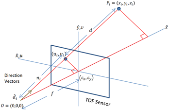 Figure 22. Pin-Hole Camera Model
 The process extracts a set of parameters commonly known as intrinsics that include nine values [k1, k2, k3, p1, p2, cx, cy, fx, fy], where [k1, k2, k3] are the radial distortion coefficients, [p1, p2] are the tangential distortion coefficients, and [cx, cy] are the coordinates of the image center, and [fx, fy] are the x and y focal distances.
The procedure takes several amplitude images of a checkerboard pattern, similar to the one shown in Figure 24. The checkerboard corners are extracted as data points used in computing the intrinsics through least-square minimization. Users wishing to learn about the theory behind lens calibration are encouraged to review the OpenCV tutorial link in the Reference section.
To perform lens calibration, first select Settings → Edit Profiles to bring up the profile window. Make sure the lens calibration checkbox is selected. Add a new profile by providing a new profile name, then click Next, and the lens calibration window as shown in Figure 23 displays.
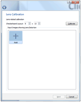 Figure 23. Lens Calibration Window
 Lens calibration will require a flat, rigid checkerboard pattern like the one shown in Figure 24. Please contact TI for the checkerboard pattern. The checkerboard should be printed on A2 sized paper.
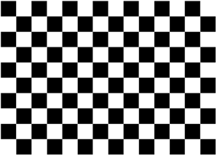 Figure 24. Checkerboard Pattern for Lens Calibration
 To start calibration, make sure the camera is running then click Add to bring up the image capture window shown in Figure 25. Some of the important considerations when performing lens calibration are:
- Filling the screen as much as possible with the entire checkerboard pattern
- Presenting the pattern in different poses—normally significant translation is not needed, it is more important to present the pattern at different orientations
- Keep the checkerboard pattern still while capturing is taking place. Multiple samples (default is 200 frames) will be captured and averaged to remove noise, before the corner points are extracted for calibration.
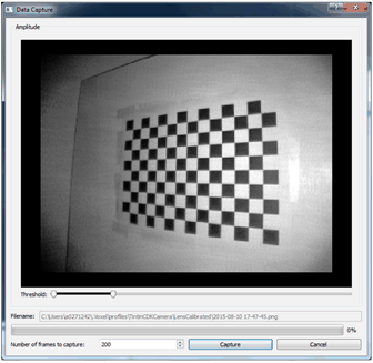 Figure 25. Checkerboard Capture Window
 One can verify whether a capture is good is by double-clicking on the captured image. Figure 26 shows a good captured image. A good capture will have a zig-zag colored pattern going through all the corner points overlaid on top of the image. If the scan pattern is in entirely in red, or if the image showed no overlaying pattern, then the capture is not good, and the captured image must be discarded and a new capture repeated.
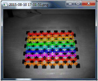 Figure 26. Example of a Good Capture
 After capturing at least 8 different views, something equivalent to the following window should result. Now click Calibrate to compute the intrinsic parameters, which will display at the bottom left-hand-corner. Click Next to conclude lens calibration.
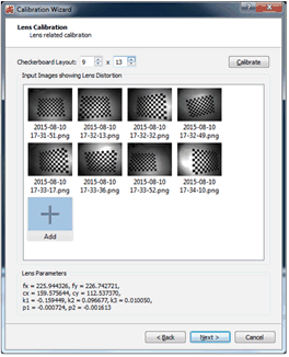 Figure 27. Lens Calibration After 8 Captures