SLAA638A august 2014 – may 2023 MSP430I2040 , MSP430I2041
- 1
- Single Phase and DC Embedded Metering (Power Monitor) Using MSP430I2040
- Trademarks
- 1 Introduction
- 2 Design Details
- 3 Calibration Techniques
- 4 Hardware Setup
- 5 Calibrator Software
- 6 Operating the PC Software Tool
-
7 Serial Communication Commands
- 7.1 Introduction
- 7.2 Communication Protocol
- 7.3
Commands
- 7.3.1 HOST_CMD_GET_METER_NAME
- 7.3.2 HOST_CMD_GET_METER_VER
- 7.3.3 HOST_CMD_GET_METER_CONFIGURATION
- 7.3.4 HOST_CMD_GET_RTC
- 7.3.5 HOST_CMD_ALIGN_WITH_CALIBRATION_FACTORS
- 7.3.6 HOST_CMD_SET_PASSWORD
- 7.3.7 HOST_CMD_GET_READINGS_PHASE_N
- 7.3.8 HOST_CMD_GET_EXTRA_READINGS_PHASE_N
- 7.3.9 HOST_CMD_SUMCHECK_MEMORY
- 7.3.10 HOST_CMD_CLEAR_CALIBRATION_DATA
- 7.3.11 HOST_CMD_SET_CALIBRATION_PHASE_N
- 7.3.12 HOST_CMD_GET_CALIBRATION_PHASE_N
- 7.3.13 HOST_CMD_SET_CALIBRATION_EXTRAS
- 7.3.14 HOST_CMD_GET_CALIBRATION_EXTRAS
-
8 Firmware and Embedded Metering Library API
- 8.1 Introduction
- 8.2
Embedded Metering LIbrary API
- 8.2.1
Embedded Metering Library Function Calls
- 8.2.1.1
Functions for Metrology Engine Control
- 8.2.1.1.1 Functions for Metrology Engine Control
- int metrology_init (void)
- int metrology_init_from_nv_data (void)
- void align_metrology_with_calibration_data (void)
- void metrology_switch_to_normal_mode (void)
- void metrology_init_analog_front_end_normal_mode (void)
- void metrology_disable_analog_front_end (void)
- 8.2.1.2 Procedure for Metrology Engine Initialization
- 8.2.1.3
Functions for Calculate and Reading the Readings
- 8.2.1.3.1 Functions for Calculate and Reading the Readings
- power_t calculate_phase_readings (void
- power_t active_power (int ph)
- power_t reactive_power (int ph)
- power_t apparent_power (int ph)
- power_t fundamental_active_power(int ph)
- power_t fundamental_reactive_power(int ph)
- power_factor_t power_factor (int ph)
- rms_voltage_t rms_voltage (int ph)
- rms_voltage_t fundamental_rms_voltage(int ph)
- thd_t voltage_thd(int ph)
- rms_current_t rms_current (int ph)
- rms_current_t fundamental_rms_current(int ph)
- thd_t current_thd(int ph)
- int16_t mains_frequency (int ph)
- uint16_t phase_status (int ph)
- 8.2.1.1
Functions for Metrology Engine Control
- 8.2.2 Embedded Metering LIbrary Callbacks
- 8.2.3
Application Level Calibration Functions
- 8.2.3.1
Functions for Reading and Writing Calibration Parameters
- 8.2.3.1.1 Functions for Reading and Writing Calibration Parameters
- int get_calibration_status (void)
- void set_calibration_status (int value)
- int clear_calibration_data (void)
- int16_t get_temperature_intercept (void)
- int16_t get_temperature_slope (void)
- void set_temperature_parameters (int16_t temperature_at_calibration, int16_t temperature_sensor_intercept, int16_t temperature_sensor_slope)
- calibration_scaling_factor_t get_P_scaling (int phx)
- void set_P_scaling (int phx, calibration_scaling_factor_t value)
- calibration_scaling_factor_t get_V_rms_scaling (int phx)
- void set_V_rms_scaling (int phx, calibration_scaling_factor_t value)
- int16_t get_v_dc_estimate (int phx)
- int16_t get_initial_v_dc_estimate (int phx)
- void set_v_dc_estimate (int phx, int16_t value)
- int32_t get_v_ac_offset (int phx)
- void set_v_ac_offset (int phx, int32_t value)
- calibration_scaling_factor_t get_I_rms_scaling(int phx);
- void set_I_rms_scaling(int phx, calibration_scaling_factor_t value);
- int32_t get_i_dc_estimate(int phx);
- int32_t get_initial_i_dc_estimate(int phx)
- void set_i_dc_estimate(int phx, int32_t value);
- int32_t get_i_ac_estimate(int phx);
- void set_i_ac_offset (int phx, int32_t value)
- uint16_t get_compensate_capacitor_value (int phx)
- void set_compensate_capacitor_value (int phx, uint16_t value)
- uint16_t get_compensate_resistance (int phx)
- void set_compensate_resistance (int phx, uint16_t value)
- int16_t get_phase_corr (int phx)
- void set_phase_corr (int phx, int16_t value)
- 8.2.3.1
Functions for Reading and Writing Calibration Parameters
- 8.2.4 Setting Default Calibration Parameters
- 8.2.1
Embedded Metering Library Function Calls
- 9 Example Application Code
- 10Hardware Design Files
- 11EVM Specification and Performance
- 12Running on MSP430i2040 and MSP430i2041
- 13Revision History
6.2 Start Using the EVM
When the EVM has been powered, some of the seven LEDs will be flashing or turned on to indicate its operation status. Some of the LEDs are not used; make changes to the provided source code to make use of all the LEDs, as necessary. The list of LEDs’ indication is listed in Table 6-1.
| LED | State | Indication |
|---|---|---|
| LED1 | ON | Background Operations Running |
| LED1 | OFF | Background Operations Completed |
| LED2 | ON | Voltage Negative Half Cycle |
| LED2 | OFF | Voltage Positive Half Cycle |
| LED3 | ON | Not used |
| LED3 | OFF | Not used |
| LED4 | ON | Foreground Operations Running |
| LED4 | OFF | Foreground Operations Completed |
| LED5 | ON | EVM is in AC mode measurement |
| LED5 | OFF | EVM is not in AC mode measurement |
| LED6 | ON | EVM is in DC mode measurement |
| LED6 | OFF | EVM is not in DC mode measurement |
| LED7 | ON | Active Energy Pulse Pulsing |
| LED7 | OFF | Active Energy Pulse Idle |
The EVM is now ready to run, launch the software “calibrator-20121120.exe” in the folder “calibration-runtime” to start communicating with the EVM. A window as shown in Figure 6-1 appears. As defined in the XML file “calibration-config.xml”, meter position 1 is assigned the serial port to communicate with the EVM, the [Comms] indicator turns green if communication to the EVM from the PC is established and it flashes between read and green when the communication is taking place.
 Figure 6-1 Calibrator Software Startup Window
Click on the [Comms] indicator in the Meter Status window as shown in Figure 6-2.
 Figure 6-2 Meter Status Window
This window shows the current reading of the meter. The background of a reading box is gray if the EVM does not support that particular reading. It turns red if the reading from EVM to that box has a large variance. It turns yellow if the reading from EVM has a fairly low variance. It turns green if the reading has a low variance. Note that the software on the PC reads the EVM every second and it also does some averaging to the data read, thus, the update rate is slower than the update rate of the EVM.
At the bottom of this window, there are four buttons:
- Click on the Meter Consumption button, which brings up the Meter Consumption window, but the EVM does not support this feature. The Meter Consumption window provides no useful information.
- Click on the Meter Calibration Factors button, which brings up the Meter Calibration Factors window (see Figure 6-3). The current calibration factor values are shown in this window.
 Figure 6-3 Meter Calibration Factor Window
 - Click on the Meter Features buttons, which brings up the Meter Features window (see Figure 6-4). In this window, the support feature of the EVM is reported in the Meters Feature window. Figure 6-4 only shows the look and feel of the meter feature window, but this is not the exact feature of the EVM.
 Figure 6-4 Meter Features Window
 - Click on the Manual Call button, which brings up the Meter Error window (see Figure 6-5). In this window, the adjustment to the calibration factor values could be done by entering the percentage error of the reading from the EVM compare to the reading from the reference meter. For more details on the technique and procedure of performing calibration, see Section 3.
 Figure 6-5 Meter Error Window
To modify the calibration factor requires the correction to be entered in the percentage error. The percentage error is calculated as shown in Equation 23:
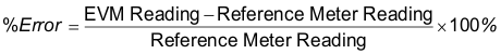
Put the percentage error in the corresponding box in the Meter Error Window (see Figure 6-5). Click Update meter and the updated calibration values will be calculated and written to the EVM. The corresponding values will be reflected in the Meter Calibration Factor Window.