SLAAEJ0 November 2023 AM625 , MSPM0L1306
2.1 A53 Core Hardware Setup
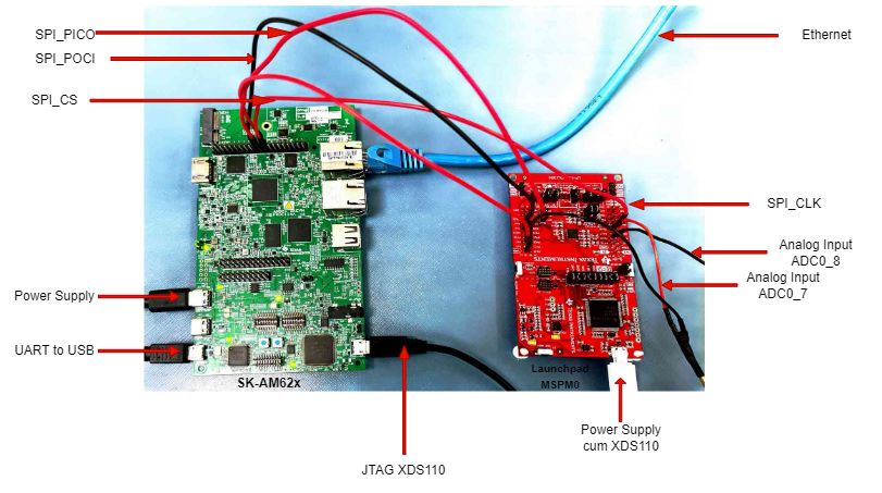
For using A53 core, the peripheral pins for SPI on SK-AM62x are present in the User Expansion Header. Figure 2-1 shows the hardware setup.
 Figure 2-1 Cable Connections between SK-AM62x (A53 Core) and LP-MSPM0L1306 for SPI communication..
 For SK-AM62x:
Connect type-C power supply with 5V adapter.
Connect UART-to-USB and USB for JTAG XDS110 to your computer.
For LP-MSPM0:
Connect power supply cum XDS110 to your computer.
Connect analog signal input to J3_PA18 (ADC0_7) in Launchpad MSPM0.
Connect analog signal input to J3_PA16 (ADC0_8) in Launchpad MSPM0 if needed.
For inter-board connections
Connect pin-19 (B13: SPI0_D0) in SK-AM62x User Expansion Connector to J2_PA4 (SPI_POCI) in Launchpad MSPM0.
Connect pin-21 (B14: SPI0_D1) in SK-AM62x User Expansion Connector to J2_PA5 (SPI_PICO) in Launchpad MSPM0.
Connect pin-23 (A14: SPI0_CLK) in SK-AM62x User Expansion Connector to J1_PA6 (SPI_CLK) in Launchpad MSPM0.
Connect pin-24 (A13: SPI0_CS0) in SK-AM62x User Expansion Connector to J2_PA3 (SPI_CS(PWM)) in Launchpad MSPM0.