SLOA227B October 2015 – March 2019 TRF7964A , TRF7964A , TRF7970A , TRF7970A
-
NFC/HF RFID reader/writer using the TRF7970A
- Trademarks
- 1 Terms, Definitions, and Symbols
- 2 Introduction
- 3 Initial RF Collision
- 4 TRF7970A Register Settings
- 5 Reader/Writer Mode
- 6 Hardware Description
- 7 Reader/Writer Firmware Example
- 8 Quick Start Guide
- 9 Operational Overview
- 10 Reader/Writer Interoperability Results
- 11 Conclusion
- 12 References
- Revision History
5.1.4 ISO15693 (Type 5 Tags)
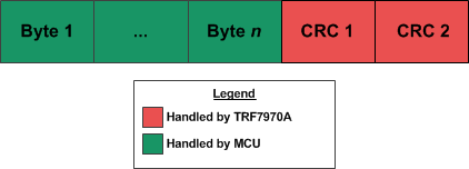
The frame format for ISO15693 packets at 26.48 kbps(see Figure 13) is based on the ISO 15693-3 Specifications. The Type 5 frame format must always include the two CRC bytes.
 Figure 13. ISO15693 Frame Format
 When the initial RF collision is completed and no RF field has been detected (see Figure 7), the ISO control register must be configured as shown in Step 1 below. Step 2 must be used to send commands to the ISO15693 tag. For more information on the initial RF collision, see Section 3.
- ISO Control Register (0x01) → 0x02 (ISO15693 at 26.48 kbps, one subcarrier, 1 out of 4, receive with CRC).
- Send packet
- Reset FIFO (0x0F) direct command.
- Transmission with CRC direct command (0x11).
- TX Length Byte 1 (0x1D) and TX Length Byte 2 (0x1E) registers.
- Write the command to the FIFO.
The provided example firmware does not contain anticollision for NFC-V/ISO15693 tags, so only one tag can be read or written to at one time.
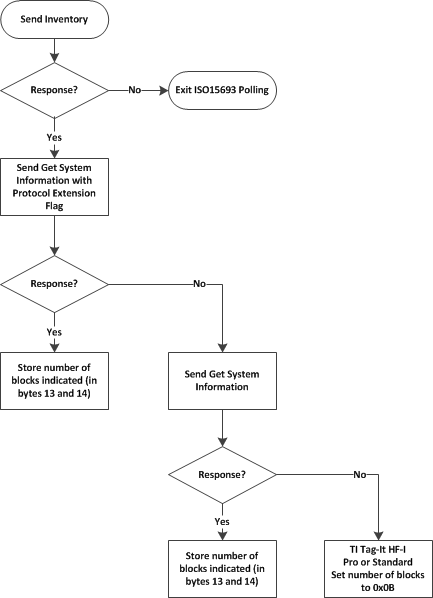
Upon reading the basic information of tag, the firmware determines the available memory size and if any special request flags must be used (such as extended protocol or option flags) based on the response to Get System Information commands (see Figure 14 for further details).
 Figure 14. Flow Chart for Determining Type 5 Tag Memory Size