SLUAAL8 may 2023 BQ25790
2 Root Cause
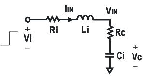
Long power adapter or battery cables have resistance and inductance. The resistance and inductance is modeled by Ri and Li in Figure 2-1. The Rc and Ci represent the input capacitance and series resistance to ground that precedes an IC's power or battery pin.
 Figure 2-1 Simplified
Equivalent Circuit During Adapter Insertion
Figure 2-1 Simplified
Equivalent Circuit During Adapter InsertionThe voltage on the charger input side VIN is given by the following mathematical model.

in which, the total impedance, Rt, is

This equation gives the voltage across capacitor Ci as

The following figures below plot VCi over time with different values for the capacitance, inductance, and resistor. Almost all power IC high current pins have some external capacitance, Ci. Figure 2-2 demonstrates that a higher Ci helps dampen the voltage spike but not eliminate the voltage spike. Figure 2-3 demonstrates the effect of the input stray inductance Li upon the input voltage spike and confirms that longer leads with higher inductance cause higher voltage spikes and long ringing. As shown in Figure 2-4, the only way to suppress the voltage ringing is to add series resistor Ri to Ci (bq24753A Host-Controlled Li-Ion and Li-Polymer Battery Charger With Low Iq and System Power Selector).
 Figure 2-2 Effect of
Capacitance on VCi
  Figure 2-3 Effect of Inductance on VCi
 Figure 2-4 Effect of Resistance on VCi