SLUUBJ1B february   2017  – july 2023 TPS2373


  1.   1
  2.   TPS2373-4EVM-758 Evaluation Module
  3.   Trademarks
  4. 1Introduction
    1. 1.1 Features
    2. 1.2 Applications
  5. 2Electrical Specifications
  6. 3Description
  7. 4Schematic
  8. 5General Configuration and Description
    1. 5.1 Physical Access
  9. 6TPS237xEVM-758 Performance Data
    1. 6.1 Startup
    2. 6.2 Transient Response
    3. 6.3 Efficiency
  10. 7EVM Assembly Drawings and Layout Guidelines
    1. 7.1 PCB Drawings
    2. 7.2 Layout Guidelines
    3. 7.3 EMI Containment
  11. 8Bill of Materials
  12. 9Revision History

PCB Drawings

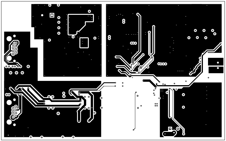
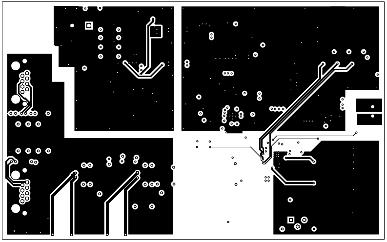
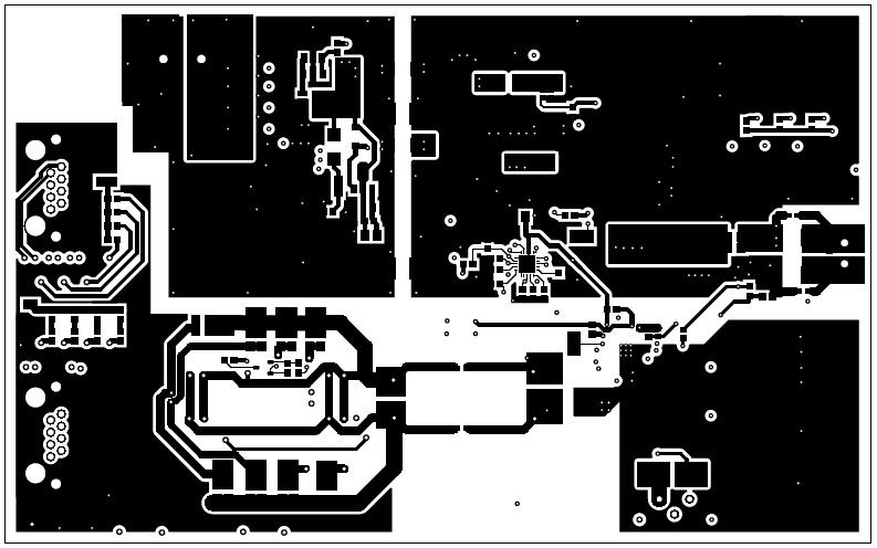
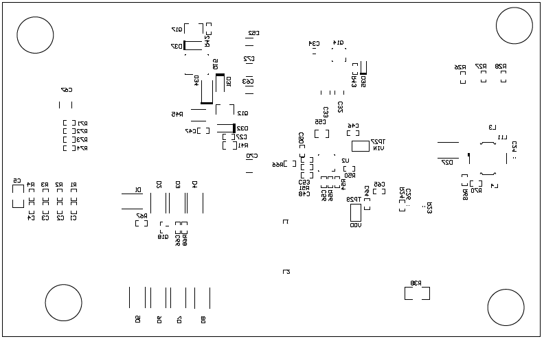
Figure 7-1 through Figure 7-6 show component placement and layout of the TPS2373-4EVM-758.
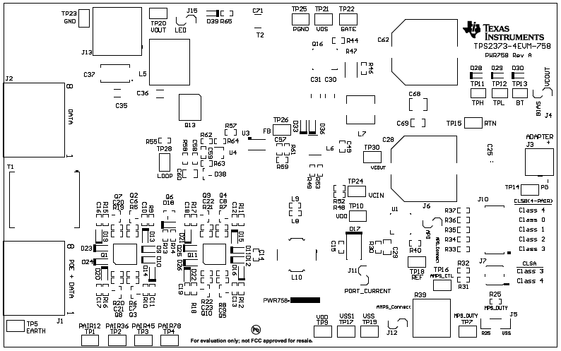
GUID-2D05D2E9-63DD-4B20-8381-B8971457655F-low.png Figure 7-1 Top Side Component Placement
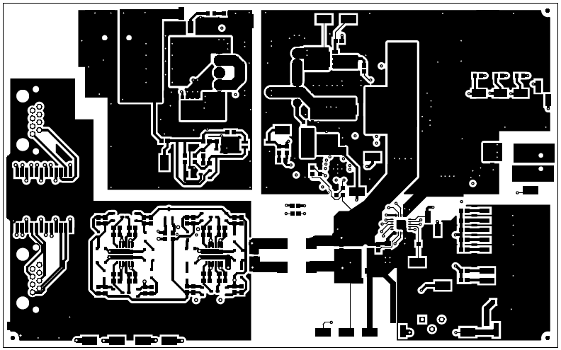
GUID-9E08EEEE-0A0A-497A-BDE4-EB62B8A3CC9C-low.png Figure 7-2 Top Side Routing
GUID-5FCED46E-14F5-46C9-A0DF-66DFC9161DD8-low.png Figure 7-3 Layer 2 Routing
GUID-25431FF7-8A51-49DE-818A-AC347E74E6CC-low.png Figure 7-4 Layer 3 Routing
GUID-97DA6122-CACA-4575-B49E-E47A722EA95E-low.png Figure 7-5 Bottom Side Routing
GUID-B78A622E-3368-4D15-A13A-8227EC84214E-low.png Figure 7-6 Bottom Component Placement