SLVAF35 February 2021 DRV8714-Q1 , TPS2HB16-Q1
5.1 Pulse Width Modulation Current Generation
It is very common to use pulse width modulation to generate a desired current waveform in the industry. The duty cycle, which is the ratio of the ON time to the period of the signal, determines the maximum and minimum currents applied to the coil with the control frequency.
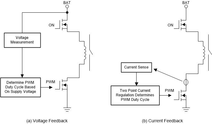
And there are two control methods typically used for the PWM control. The first one is voltage feedback, the other one is current feedback. The voltage feedback is an open loop control for current. It measures the supply voltage and sets the duty cycle accordingly. Even though it is a low-cost realization with simple hardware circuit, the current accuracy is poor and a large margin is always left in order to ensure proper operation. Besides, additional effort of pre-calibration work is necessary to get a voltage-duty cycle map for different contactors.
 Figure 5-2 Pulse Width Modulation Current Generation.
 The current feedback is a closed loop control for current. It measures the coil current all the time and toggles the switches according to the current directly. This can ensure high current accuracy and make the coil current highly consistent with the required current. In addition, voltage-duty cycle map is no longer needed and save the pre-calibration effort. However, the cost of this current feedback approach is probably more expensive than the voltage feedback solution.