SLVAFJ1 February 2023 TPS2121
1 Introduction
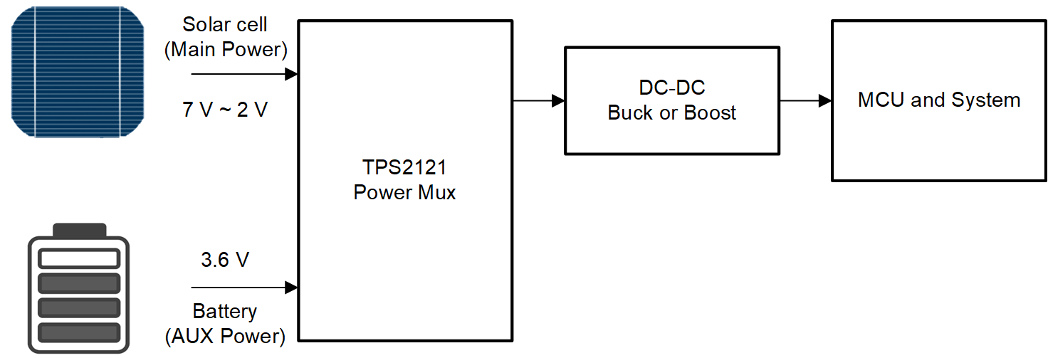
This design example uses solar cell as a main power source which is a variable source. Main power needs to source the VOUT while it is above the backup power. However, main power can fall below backup power due to weather conditions. If the main power is low, then the system needs to switchover to a backup power source without interrupting normal operation. Without the switchover, this could cause the downstream load to reset or enter an undervoltage lockout condition. The battery is generally used as backup power to maintain minimum VOUT for the system.
Battery must last as long as possible to run the system without interrupting normal operation. To maximize the battery run time, leakage current from the battery needs to be minimized. TPS2121 supports ISBY = 25 µA (max) for disabled input power. With VCOMP mode configuration, TPS2121 can support automatic switchover and minimizes leakage current. Therefore TPS2121 can minimize the leakage current from the battery when the main power is selected as VOUT to the system. See GUID-8BA976C1-CC4B-4B87-B9B8-7C5F98A8406C.html#GUID-8BA976C1-CC4B-4B87-B9B8-7C5F98A8406C for detail about this.
TPS2121 has additional features like over-voltage protection, fast reverse current blocking, active current limiting, and soft start control. Large input capacitors are recommended if switching between high current rails. The capacitors help to provide a temporary power source for stable switchover.
 Figure 1-1 Simplified Block Diagram