SLVUBX1 December 2020 TPS63810
2.3 Step 3: Hardware Setup
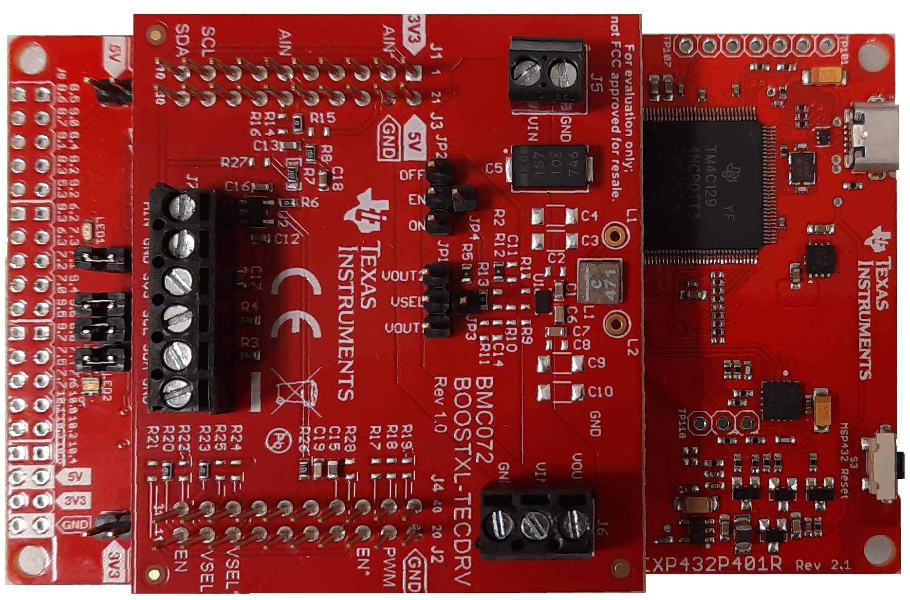
After the firmware file has successfully downloaded to the LaunchPad, unplug the USB cable from the LaunchPad. Align properly the connectors (as shown in Figure 2-1) and attach the BOOSTXL-TECDRV BoosterPack to the bottom set of connectors on the LaunchPad.
 Figure 2-1 LaunchPad and BoosterPack Combo
When the BoosterPack is attached, plug the USB cable into the bottom connector of the LaunchPad and also to the PC. A green LED lights up indicating that the LaunchPad is powered. The LaunchPad communication to the PC is USB communications device class (CDC) using a virtual COM port. Windows® 10 automatically installs the required driver. Earlier versions of the operating system may require a manual driver installation.
Connect the temperature sensor to the sensor input terminal block J7 on the BoosterPack. Depending on the temperature sensor, different connectors need to be used. Details regarding these steps can be found in Section 7. Make sure that the jumper on JP2 header is connecting EN and ON pins, and that the jumper on JP1 header is connecting VSEL and VOUT1 pins.
Connect the TEC module to the output terminal block J6 on the BoosterPack, minding the TEC module polarity.
Connect the 3.3-V power supply to the input power terminal block on the BoosterPack, and turn the power supply on.