SLYY150B may 2020 – august 2023 OPA855 , OPA857 , OPA858 , OPA859
LIDAR types
Among the different types of LIDAR systems available, in this paper we will focus primarily on the narrow-pulsed ToF method. There are two types of beam steering in LIDAR systems:
- Mechanical LIDAR uses high-grade optics and a rotating assembly to create a wide (typically 360-degree) FOV. The mechanical aspect provides a high signal-to-noise ratio (SNR) over a wide FOV, but results in a bulky implementation (although this has also been shrinking).
- Solid-state LIDAR has no spinning mechanical components and a reduced FOV; thus, it is cheaper. Using multiple channels at the front, rear and sides of a vehicle and fusing their data creates an FOV that rivals mechanical LIDAR.
Solid-state LIDARs have multiple implementation methods, including:
- Microelectromechanical systems (MEMs) LIDAR. A MEMS LIDAR system uses tiny mirrors whose tilt angle varies when applying a stimulus such as a voltage. In effect, the MEMS system substitutes mechanical scanning hardware with an electromechanical equivalent. The receiver light collection aperture that determines the receive SNR is typically quite small (a few millimeters) for MEMS systems. To move the laser beam in multiple dimensions requires cascading multiple mirrors. This alignment process is not trivial, and once installed, it is susceptible to shocks and vibrations typically encountered in moving vehicles. Another potential pitfall with a MEMS- based system is that automotive specifications start at –40°C, which can be challenging for a MEMS device.
- Flash LIDAR. Flash LIDAR operation is very similar to that of a standard digital camera using an optical flash. In flash LIDAR, a single large-area laser pulse illuminates the environment in front of it and a focal plane array of photo detectors placed in close proximity to the laser captures the back-scattered light. The detector captures the image distance, location and reflected intensity. Since this method captures the entire scene in a single image compared to the mechanical laser scanning method, the data capture rate is much faster. In addition, since the entire image is captured in a single flash, this method is more immune to vibration effects that could distort the image. A downside to this method is the presence of retroreflectors in the real-world environment. Retroreflectors reflect most of the light and back-scatter very little, in effect blinding the entire sensor and rendering it useless. Another disadvantage to this method is the very high peak laser power needed to illuminate the entire scene and see far enough.
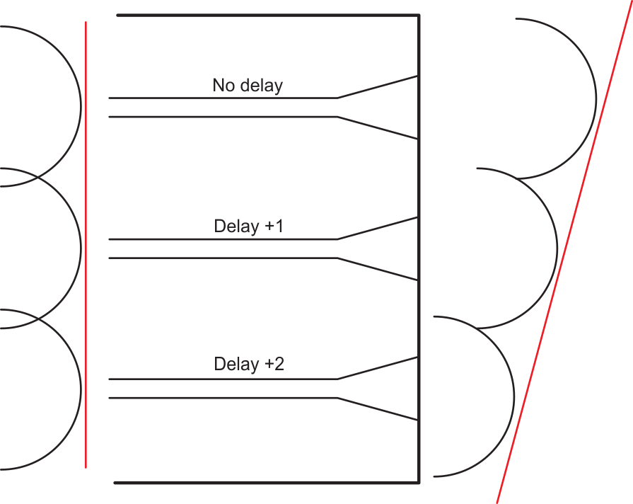
- Optical phase array (OPA).
The OPA principle is similar to phased-array radar. In an OPA system, an optical
phase modulator controls the speed of light passing through the lens.
Controlling the speed of light enables control of the optical wave-front shape,
as shown in Figure 2. The top beam is not delayed, while the middle and bottom beams are delayed
by increasing amounts. This phenomenon effectively “steers” the laser beam to
point in different directions. Similar methods can also steer the back-scattered
light toward the sensor, thus eliminating mechanical moving parts.
 Figure 2 An OPA.
 - Frequency-modulated continuous wave (FMCW) LIDAR. While the methods listed so far are based on the ToF principle using narrow light pulses, FMCW LIDAR uses a coherent method, producing brief chirps of frequency- modulated laser light. Measuring the phase and frequency of the return chirp enables the system to measure both distance and velocity. The computational load and optics are a lot simpler with the FMCW method, although the chirp generation adds complexity.