SNVA998 September 2020 LP8732-Q1 , LP87522-Q1
2 Power Solution
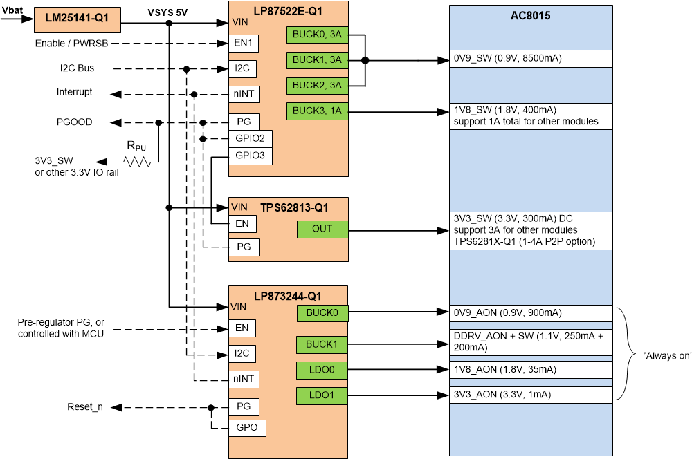
Figure 2-1 shows an example block diagram of LP87522E-Q1, LP873244-Q1, and TPS62813-Q1 devices powering the AC8015 power rails. LM215141-Q1 is used as a pre-regulator to generate 5V input voltage for the PMICs and TPS62813-Q1 buck regulator.
LP87522E-Q1 and LP873244-Q1 are specific part numbers for this platform and have the output voltages, sequencing etc. pre-programmed to the OTP memory. Please refer to the Technical Reference Manual for these part numbers for details on the OTP settings.
 Figure 2-1 AC8015 Power Solution Block
Diagram
Figure 2-1 AC8015 Power Solution Block
DiagramMain features:
- After the devices are powered, the microcontroller can control the EN signals of LP873244-Q1 and LP87522E-Q1. LP873244-Q1 can be enabled/disabled with the pre-regulator powergood signal as well.
- Startup delays are controlled internally in the LP87522E-Q1 and LP873244-Q1 logic and TPS62813-Q1s is controlled with LP87522E-Q1 GPIO3. Section 3 has more details about the startup/shutdown sequence.
- I2C can be used to read status registers and reset interrupts. Since interrupt lines are connected together, both PMIC fault registers should be read/cleared in case of interrupt goes low.
- All PMIC devices have dedicated I2C address so they can share the same I2C bus.
- LP873244-Q1 GPO signals act as nRESET signal for the SoC and LP87522E-Q1 GPIO2 signal is used as PGOOD indication. Note the PGOOD functionality is disabled in the PMIC configuration, although it can be enabled through I2C bus.