SPRACO3 October 2019 INA240 , LMG5200 , TMS320F280021 , TMS320F280021-Q1 , TMS320F280023 , TMS320F280023-Q1 , TMS320F280023C , TMS320F280025 , TMS320F280025-Q1 , TMS320F280025C , TMS320F280025C-Q1 , TMS320F280040-Q1 , TMS320F280040C-Q1 , TMS320F280041 , TMS320F280041-Q1 , TMS320F280041C , TMS320F280041C-Q1 , TMS320F280045 , TMS320F280048-Q1 , TMS320F280048C-Q1 , TMS320F280049 , TMS320F280049-Q1 , TMS320F280049C , TMS320F280049C-Q1 , TMS320F28374D , TMS320F28374S , TMS320F28375D , TMS320F28375S , TMS320F28375S-Q1 , TMS320F28376D , TMS320F28376S , TMS320F28377D , TMS320F28377D-EP , TMS320F28377D-Q1 , TMS320F28377S , TMS320F28377S-Q1 , TMS320F28378D , TMS320F28378S , TMS320F28379D , TMS320F28379D-Q1 , TMS320F28379S
-
Dual-Axis Motor Control Using FCL and SFRA On a Single C2000 MCU
- Trademarks
- 1 Introduction
- 2 Benefits of the C2000 for High-Bandwidth Current Loop
- 3 Current Loops in Servo Drives
- 4 PWM Update Latency for Dual Motor
- 5 Outline of the Fast Current Loop Library
- 6 Evaluation Platform Setup
- 7 System Software Integration and Testing
- 8 Summary
- 9 References
3 Current Loops in Servo Drives
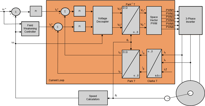
Figure 1 shows the basic speed control block diagram of a field oriented control (FOC) based AC motor control system used in servo drives. The current loop is highlighted here because this is the inner most loop and has a higher influence on the bandwidth of the outer speed and position loops. For the outer loop to have a higher bandwidth, the inner loop must have a far higher bandwidth, typically more than three times.
 Figure 1. Basic Scheme of FOC for AC Motor
 In the current loop, any two of the motor phase currents are measured, while the third can be estimated from these two sensing currents. These measurements feed the Clarke transformation module. The outputs of this projection are designated Iα and Iβ. These two components of the current along with the rotor flux position are the inputs of the Park transformation, which transform them to currents (Id and Iq ) in D-Q rotating reference frame. The Id and Iq components are compared to the references Idref (the flux reference) and Iqref (the torque reference). At this point, the control structure shows an interesting advantage; it can be used to control either synchronous (PM) or asynchronous (ACIM) machines by simply changing the flux reference and obtaining the rotor flux position. In the synchronous permanent magnet motor, the rotor flux is fixed as determined by the magnets, so there is no need to create it. Therefore, when controlling a PMSM motor, Idref can be set to zero, except during field weakening. Unlike PM motor, ACIM motors do not have a rotor flux by default. Since the flux need to be created, the flux reference current must be greater than zero.
The torque command Iqref can be fed from the output of the speed regulator. The outputs of the current regulators are Vdref and Vqref. These outputs are applied to the inverse Park transformation. Using the position of rotor flux, this projection generates Vαref and Vβref, which are the components of the stator vector voltage in the stationary orthogonal reference frame. These components are the inputs of the PWM generation block. The outputs of this block are the signals that drive the inverter.
Both Park and inverse Park transformations need the rotor flux position. Obtaining this rotor flux position depends on the choice of AC machine observer in sensorless control or the position encoder in the case sensored control.