SPRACR5A february 2020 – may 2023 AWR2243
2.2 Bootmode – SPI
In functional mode, if no valid image header is found in the predefined SDF location, the bootloader will enter the SPI based bootloading mode.
This involves the following steps:
- Pinmux the SPI pins - [SPI_MOSI: Ball R8, SPI_MISO: Ball P5, SPI_CLK: Ball R9, SPI_CS_N: Ball R7 and SPI_HOST_INTR: Ball P6 of AWR2243 device]
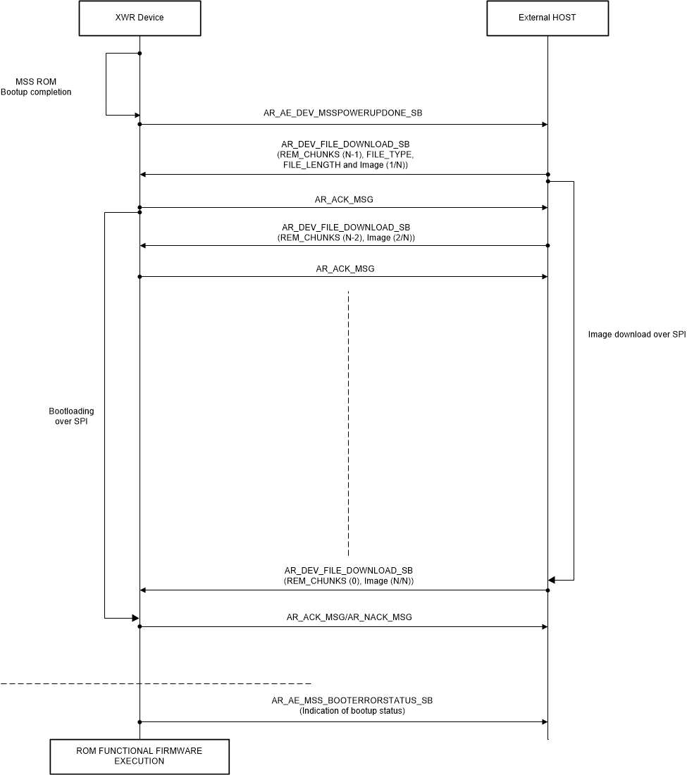
- Follows the “Communication Protocol” as defined in the Radar Interface Control document to communicate with an external host to receive the images to be loaded as message packets over SPI.
- Once the load of all images is complete, the patches to the ROM get applied and then the functional firmware begins execution that could then receive control API commands over SPI and send out the data over the high speed interfaces (LVDS/CSI2).
The handshake with the external host is as depicted in Figure 2-4.
 Figure 2-4 Bootmode - SPI