SPRADB7 September 2023 AM2431 , AM2432 , AM2434 , AM2631 , AM2631-Q1 , AM2632 , AM2632-Q1 , AM2634 , AM2634-Q1 , AM263P4-Q1 , AM2732 , AM2732-Q1
- 1
- Abstract
- Trademarks
- 1Introduction
- 2Thermal Resistance Overview
- 3Board Design Choices that Affect Thermal Performance
- 4Thermal Design Best Practices Review
- 5AM263x EVM Thermal Comparison with Data
- 6Using the Thermal Model
- 7References
3.5 Relative Position of Heat Emitters
The AM263x device is not the only package that is dissipating heat on a PCB. It is important to make a conscious effort to separate all heat-releasing components or else the thermal resistance between the board and ambient temperature will suffer as a result. Examples of components that run warmer include but are not limited to:
- Other processors or microcontrollers
- Power Management Integrated Chips (PMIC)
- Voltage regulators
- LIN and Ethernet PHY
For best thermal performance:
- Ensure that there is sufficient distance between known heat emitters on the PCB.
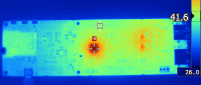
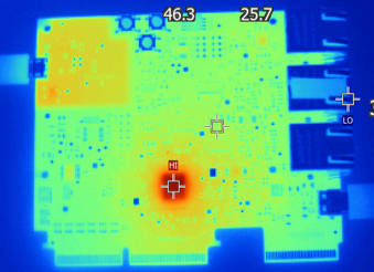
Figure 3-3 shows how the LaunchPad was designed to separate low-dropout (LDO) voltage regulator's heat radiation from the AM263x device. The AM263x Control Card is designed with a heat-emitting package near the SoC but the package is responsible for supplying the 25 MHz clock to the SoC. In this instance, the signal integrity of the operating clock is more important than impacting thermal resistance. Because the control card follows other thermal design rules listed in this document, it is easy to overlook the potential impact of one heat-emitting package near the SoC. Figure 3-4 shows the thermal camera view of the AM263x Control Card.
 Figure 3-3 LP-AM263x Thermal Camera
 Figure 3-4 TMDS263CNCD Thermal Camera