SSZT370 november 2019 DRV8889-Q1
Stepper motors are popular in vehicle lighting systems for headlight leveling and steering. As automakers transition to quieter electric vehicles, noise reduction in these systems becomes more important and requires a well-tuned stepper motor with the ability to detect stall conditions. This is particularly true for automotive lighting systems, where the motor needs to detect the “end of travel” for headlights.
Tuning a stepper motor system is time-consuming and involves trade-offs related to the supply voltage, motor winding inductance and resistance. Smart tuning can help engineers overcome these trade-offs for ripple control by automatically selecting the optimal current regulation scheme and eliminating the need for tuning. Additionally, back-electromotive force (EMF) sensing methods provide a stall detection function to reduce the noise at endstops. It is important to consider electromagnetic interference (EMI) when there are long cables from the electronics to the lightning assemblies.
In automotive stepper motor applications such as headlights and head-up displays (HUDs), the system needs to know if the motor is stalled or if the motor has reached “end of travel” to avoid overdriving the motor, which can result in power loss or mechanical noise.
To help detect stall conditions more accurately, TI has implemented a new current-regulation scheme in our DRV8889-Q1 motor driver. Traditional schemes use fixed off-time regulation. But smart tuning for ripple control controls the current between a peak value (ITRIP) and a lower level (IVALLEY), resulting in a variable pulse-width modulation (PWM) off time that can be monitored.
| Achieve sensorless stall detection | |

|
Learn how the DRV8889-Q1 motor driver implements a novel approach for sensorless stall detection of stepper motors by using the PWM OFF-time to sense the back EMF. |
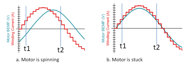
A stall detection algorithm compares the back-EMF between the rising and falling current quadrants by monitoring the PWM off time and generates a value represented by the 8-bit register TRQ_COUNT. The comparison is done in such a way that the TRQ_COUNT value is practically independent of the motor current, motor winding resistance, ambient temperature and supply voltage. For a lightly loaded motor, the TRQ_COUNT will be a nonzero value, as the back-EMF is different between t1 and t2, as shown in Figure 1. If the motor approaches a stall condition, TRQ_COUNT will approach zero, as the back-EMF is the same between the two quadrants. After detecting a stall condition, the system controller can stop sending the step signal and reduce the winding current, which will in turn reduce audible system noise and power consumption.
 Figure 1 Motor back-EMF vs. winding
current
Figure 1 Motor back-EMF vs. winding
currentAs cable harnesses become longer in automotive vehicles, it is important to consider EMI mitigation techniques in motor drivers. Stepper motor drivers use a PWM technique to regulate the output current. There are two switching power converter EMI control methods that you can apply to motor drive systems.
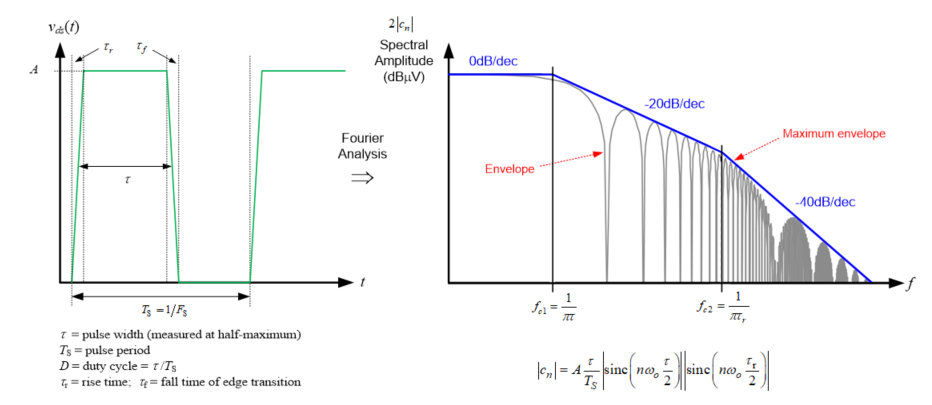
For a switching converter, the slew rate is related to the switching noise roll-off frequency. The 40-dB/dec roll-off frequency is inversely proportional to the slew rate of the driver. By changing the slew rate from 100 V/µs to 10 V/µs, the 40 dB/dec switching noise roll-off frequency will be one decade earlier, which will push the noise down 40 dB and significantly improve the EMI performance, as shown in Figure 2. The DRV8889-Q1 has four slew-rate settings that are configurable through a serial interface.
 Figure 2 EMI noise vs. switching
converter slew rate
Figure 2 EMI noise vs. switching
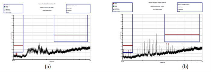
converter slew rateSwitching converter EMI noise is a function of the converter’s switching frequency and its harmonics. The second method is a spread-spectrum technique that modulates the switching frequency and dithers the PWM clock, which distributes the noise energy to other frequencies and lowers the peak frequency energy. Figure 3 shows the EMI test result with the spread-spectrum clocking function enabled and disabled on the DRV8889-Q1 evaluation module.
 Figure 3 EMI noise vs. spread spectrum
with 12 VM; a 100-V/µs slew rate; 1/32 microstep; 1,000 step pulses
per second; 1-A full scale current and ripple control dynamic decay: enabled
(a); and disabled (b)
Figure 3 EMI noise vs. spread spectrum
with 12 VM; a 100-V/µs slew rate; 1/32 microstep; 1,000 step pulses
per second; 1-A full scale current and ripple control dynamic decay: enabled
(a); and disabled (b)The DRV8889-Q1 stepper motor driver offers three main benefits when using stepper motors in automotive, HUD, engine and motorbike applications. The smart tuning for ripple control algorithm automatically adjusts the current regulation behavior to minimize ripple and noise in the system. The algorithm also gives you a value proportional to back-EMF that you can use to determine when a headlight has hit an endstop and minimize the rattling noise that can result from over-travel. Finally, EMI countermeasures have been incorporated in the DRV8889-Q1 to reduce EMI.