SSZT667 july 2018 DRV10987
Today, the awareness of the environment and energy savings is as high as ever before. New generations of large household appliances such as washers, dryers and refrigerators must have higher performance parameters such as better efficiency and reduced electromagnetic interference. System flexibility must be high to facilitate market modifications and reduce development time. Designers must make all of these improvements while at the same time decreasing system cost.
Driven by the efficiency and costs, brushless DC (BLDC) motors have become more and more popular in household appliances. You can now find them in washing machines, air conditioners, refrigerators and more. Unlike the brushed DC motors and AC motors, BLDC motors have many methods to drive. Each driver method has its own pros and cons which we discuss in the post.
The Importance of the BLDC Driver Control Method
The BLDC motor’s electronic commutator sequentially goes from u phase to v phase to w phase and energizes the stator coils, generating a rotating electric field that “drags” the rotor around with it. Efficient operation relies on precise energizing of the coils depending on the relative stator and rotor positions. BLDC motors use either sensor or sensorless feedback for rotor positional feedback.
In a sensor design, three Hall-effect sensor integrated circuits (ICs) are mounted in a location near the motor stator. The timing of Hall sensor IC transitions corresponds to the back-electromotive force (BEMF) zero crossings. In sensorless technology, drivers depend on the timing of the motor BEMF zero voltage crossing.
Many applications are shifting to sensorless drivers because they eliminate the Hall-effect sensor IC and associated circuitry in a motor design. BEMF is a function of velocity where there is zero BEMF at startup. Sensorless designs require complex open-loop startup algorithms in order to accelerate the motor to a speed where the BEMF is detectable. A Hall-commutated driver always detects the rotor position so that startup is dependable, but adds additional cost to the motor assembly.
There are three control schemes for electronic commutation:
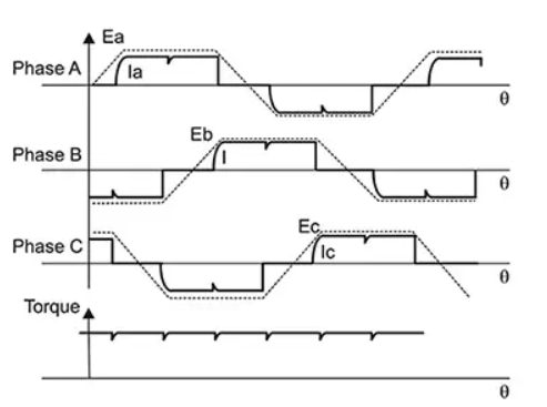
- Trapezoidal. The
trapezoidal technique shown in Figure 1 energizes two phases, with one phase feeding current to the
motor and the other providing a current return path. The third phase is not
driven. The driver controls which two switches in the three-phase driver must be
controlled positively or negatively in order to energize the two active coils.
As the motor turns, the current to the motor terminals is commutated every 60
degrees of rotation. The advantage of the trapezoidal method is that it is the
easiest to implement; the downside is that this stepped commutation causes
torque ripple. Torque ripple can cause speed changes, which can lead to
vibration and audible noise.
 Figure 1 Trapezoidal Control
and Torque Ripple
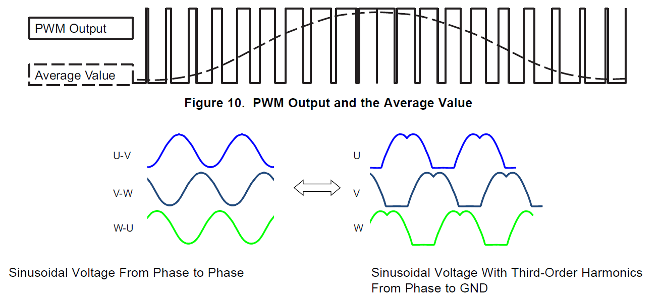
 - Sinusoidal. Pure sinusoidal drive voltages are rarely used in actual designs because they don’t provide enough voltage for each motor terminal with respect to ground. A better method is to generate sinusoidal differential
voltages between phases, shifted by 120 degrees for commutation, by varying the pulse-width modulation (PWM) duty cycle (and thus the drive voltages) relative to ground using a “saddle” profile (Figure 2). The resulting phase current driving the motor then follows the pure sine-wave variation of the
phase-to-phase voltage. The saddle profile technique offers two advantages: First, the maximum differential voltage generated is higher than what a pure sinusoidal signal can produce, offering higher torque and speed for a given input.
Second, each terminal output is zero for one-third of the time, further reducing switching losses in the power stage.
 Figure 2 Saddle Profile Sinusoidal Control
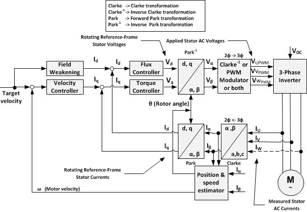
 - Field-oriented control (FOC). The FOC control method identifies the stator currents of a three-phase AC electric motor as two orthogonal components that can be visualized with a vector (Figure 3). One component defines the magnetic flux of the motor; the other component defines the torque. The
control system of the drive calculates the corresponding current component references from the flux and torque references given by the drive’s speed control. The current proportional-integral (PI) control method controls the driver’s
PWM output.
 Figure 3 FOC Control Theory
After analyzing the three control methods, FOC has complex arithmetic to trace motor torque and requires a high-performance microcontroller (MCU). Trapezoidal control is easy to achieve with a BEMF detection analog circuit, but will generate torque ripple and noise at every commutation. Sinusoidal control will calculate the BEMF during the commutations, but the calculation will fail if the load suddenly changes. Figure 4 compares each control method.
 Figure 4 Comparison of BLDC
Motor-Control Methods
Figure 4 Comparison of BLDC
Motor-Control MethodsAppliances have a stable load of drain pumps and fans, which makes the sinusoidal control scheme the best fit because of its low cost, low torque ripple, low audible noise and low response time. TI’s DRV10987 BLDC motor driver is a single-chip sinusoidal solution for 50W BLDC motors used in washer drain pumps and dryer fans. Sinusoidal control reduces noise by as much as 13dB and increases efficiency by as much as 10%, as you can see in the “DC Motor – Water Pump Demonstration” video.
The DRV10987 integrates control logic with metal-oxide semiconductor field-effect transistors (MOSFETs). You can control the motor by analog voltage, PWM or I2C interface. With DRV10987, you can design a compact driver in a small form factor.
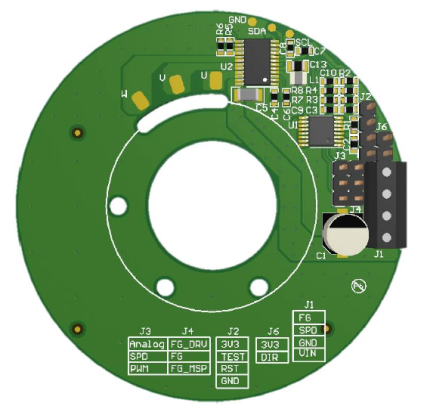
The 24V, 36W Sensorless BLDC Sinusoidal Motor Drive with Closed-Loop Speed Control Reference Design shown in Figure 5 goes into more detail on closed-loop speed control with the DRV10987.
 Figure 5 24V, 36W Sensorless BLDC Motor
Drive with Closed-Loop Speed Control Reference Design
Figure 5 24V, 36W Sensorless BLDC Motor
Drive with Closed-Loop Speed Control Reference DesignThe DRV10987 also integrates full protection logic to achieve the robust motor driver control method required by appliances like washing machines and refrigerators. The overcurrent protection circuit performs phase-to-phase, phase-to-GND and phase-to-VCC short-circuit protection. The integrated current limitation logic can limit the phase current within the MOSFET’s peak current ability (3A). The rotor-lock detection has a fast and accurate method to detect the lose position and rotor lock condition. Anti-voltage surge (AVS), overvoltage and undervoltage protections can prevent the chip from being damaged by a DC bus fault. For a robust system design, integrated thermal protection can prevent the chip from being damaged by overheating. With the help of integrated robust control logic, you can easily develop your own motor driver board that is suitable for your application within a short period of time.
The technology discussed in this post gives you an opportunity to design a high-efficiency, high-performance BLDC motor driver board easily. The sinusoidal sensorless BLDC motor driver will help you achieve appliance applications with better performance on torque ripple, audit noise and more.
Additional Resources
-
Check out our blog on the integrated intelligence features of TI’s motor drivers.
-
Learn more about the DRV10987 evaluation module.