SSZT695 june 2018 TMS320F28379D
In part 1 of this blog series, I gave an overview of the market opportunity for EtherCAT® slave stack support on C2000™ microcontrollers (MCUs) and an introduction to a three-phased solution to jump-start slave stack development. In part 2, I outlined what is different and compelling about the TI C2000 MCU EtherCAT implementation. In this installment, I’ll break down the three phases of the development of your own slave-node application and how the TI EtherCAT package in C2000 controlSUITE™ software supports each phase.
Given the previously outlined complementary aspects of EtherCAT technology and C2000 MCUs for motion control applications – and because of customer requests – TI applied its embedded software development experience and C2000 MCU architecture knowledge to create a set of software solutions designed to aid in the development of EtherCAT slave nodes on C2000 real-time control MCUs. The software package will help you:
- Evaluate the stack for a slave node.
- Validate the correct operation/hookup of your custom hardware.
- Create a complete slave-node application using your hardware and a stack distributed by the EtherCAT Technology Group.
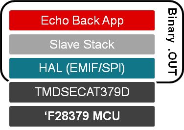
Step 1: Evaluate the C2000 EtherCAT Node (Stack and Hardware)
 Figure 1 C2000 MCU Out-of-the-box EtherCAT Slave Demonstration and Evaluation Solution
This evaluation project will help you answer questions like: What is the transfer latency from the external EtherCAT controller (ET1100) to the C2000 MCU? How much central processing unit (CPU) bandwidth does this solution take? What is the memory footprint of the hardware abstraction layer (HAL) and the slave stack?
After downloading the latest controlSUITE software, you can install the demonstration and evaluation example by executing the setup file, “EtherCAT_Slave_Demo_Code_v01_00_00_00_setup,” in the controlSUITE development kit project.
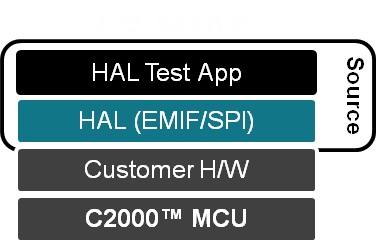
Step 2: Validate Your EtherCAT Hardware
You do not need an EtherCAT slave stack to validate the hardware connection in this case. Unlike step 1, the HAL test project is available as source code to aid in validation or to adapt C2000 MCUs to other physical interfaces for EtherCAT controllers.
 Figure 2 C2000 MCU HAL Test Application
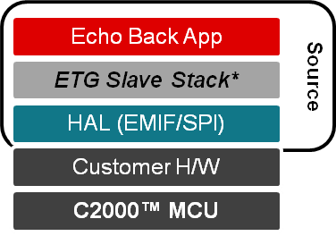
Step 3: Create Your Own EtherCAT Slave-node Solution
 Figure 3 C2000 MCU Native EtherCAT Slave Stack Reference Development Framework
In the event that your version of the configuration tool does not include support for C2000 MCUs, the controlSUITE project includes a patch that will make C2000 MCUs (and the ASYNC16 and SPI PDI options) available to you in the drop-down processor selection dialog box.
Two project configurations are available:
- A random access memory (RAM)-based project, which is usually helpful during the initial stages of a project when code changes are frequent (less time spent programming flash).
- A flash-based project, when the code is more mature and ready for testing through power-cycling of the target C2000 MCU.
With the release of the EtherCAT Slave and C2000 Delfino™ MCU controlCARD kit and EtherCAT solution reference in controlSUITE, software you can jump-start the development of an EtherCAT slave stack running directly on C2000 MCUs.
Additional Resources
- Purchase the C2000 EtherCAT controlCARD.
- To learn more about TI’s EtherCAT slave-node solutions for C2000 MCUs, check out: