SSZT791 february 2018 TPS92610-Q1
CHMSL stands for the center high-mounted stop lamp. In a vehicle, the CHMSL is mounted above the left and right brake lights (also called stop lamps). According to the National Highway Traffic Safety Administration, when brakes are applied, the CHMSL provides a conspicuous and unambiguous message to drivers of the following vehicles that they must slow down. Since the CHMSL is mounted in addition to the left and right brake lights, it is also known as the “third brake light.” Some vehicles, such as pickup trucks, feature a reverse light integrated in the CHMSL in addition to the brake light function.

A CHMSL Implementation Using Discrete Components
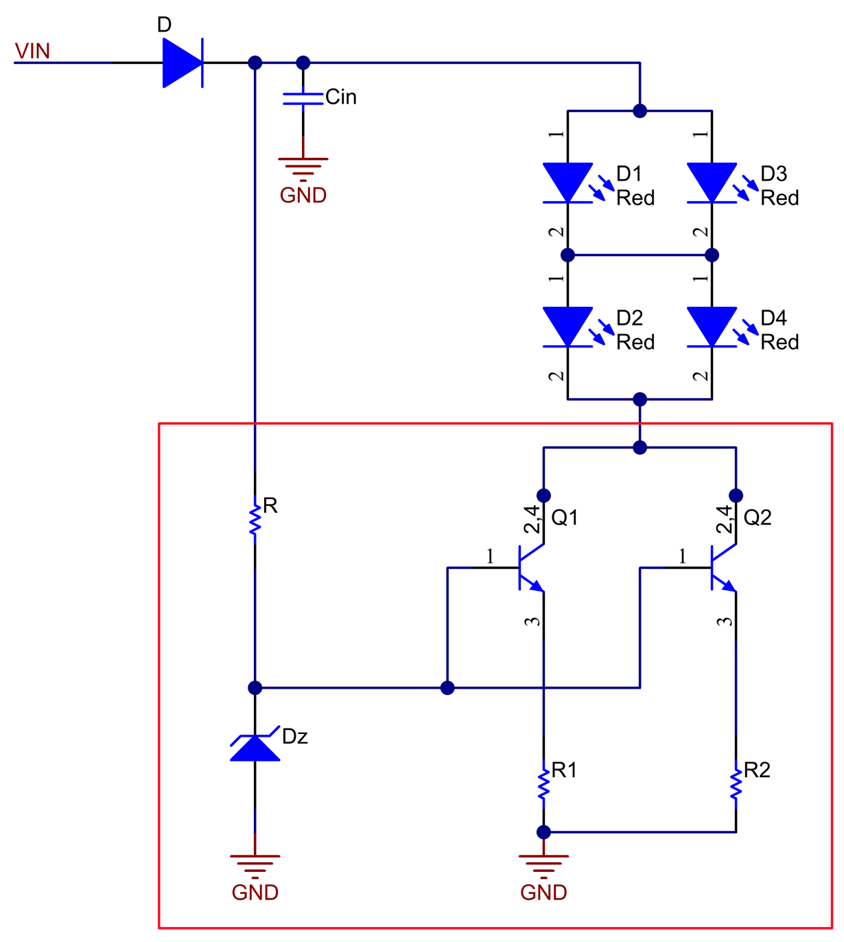
Thermal Considerations

Equation 2 calculates the maximum power dissipation of the BJTs to 0.81W:

Assuming the maximum operating ambient temperature is 85°C, and by using BJTs in the small-outline transistor (SOT)-223 package with a thermal resistance of 80°C/W, Equation 3 calculates the maximum BJT junction temperature as:

This calculation shows the junction temperature is very close to the typical maximum allowable junction temperature of 150°C.
In order to improve the circuit’s thermal performance, using two transistors in parallel splits the power dissipation, enabling the maximum temperature to stay below 150°C even in worst-case conditions, as shown by the calculation in Equation 4:

When using a different BJT package type with a higher thermal resistance, you need more BJTs to split the power dissipation. The number and size of transistors in parallel is mainly based on the LED current and the maximum power dissipation allowed in the transistors.
A CHMSL Implementation Using Integrated LED Driver ICs
 Figure 1 TPS92610-Q1 integrated LED driver circuit
Thermal Considerations Again

Assuming the same 90mA of current, a maximum voltage drop of 11V on the IC and a thermal resistance of 52°C/W, Equation 6 calculates the maximum junction temperature:

136.5°C is well below the maximum specified IC junction temperature of 150°C. Thus, you need only one driver IC to operate the example CHMSL LED strings.
Advantages of an Integrated Solution
The third advantage of a linear LED driver IC-based solution is its diagnostic features, which enable the detection of LED circuit faults such as LED opens and shorts, and notify the driver of faults.
Finally, the implementation shown in Figure 1 could be cheaper than the implementation in Figure 1 when considering the number of components and the cost of each component.