SSZT948 september 2017
Many places, including factories, office buildings and large stores, require the operation of industrial motors to control ventilation and operate escalators, elevators and other machinery. These motors require periodic maintenance that can often prove expensive, while also causing downtime that can interrupt and delay important tasks. Monitoring motors for signs of wear and damage is vital to ensuring the success of the overall system.
Motor monitoring is an example of using predictive analytics to schedule preventative maintenance to reduce cost and decrease downtime. Predictive analytics are becoming very important in many industries as a way of predicting future events with currently available data, and preventative maintenance is one prominent example of using this information to gain an advantage.
In the past, employees attached a large monitor to each motor individually to collect data about its health. This is time-consuming and can only occur so often, thus reducing the chance that an issue with a motor will be caught quickly. Additionally, this procedure requires a motor location that’s easily accessible by the person taking the measurements.
To overcome these obstacles, small wireless monitors placed in hard-to-reach locations do not need human access to take measurements. These monitors send measurements wirelessly to another device that stores the data without anyone having to physically attach anything to a motor.
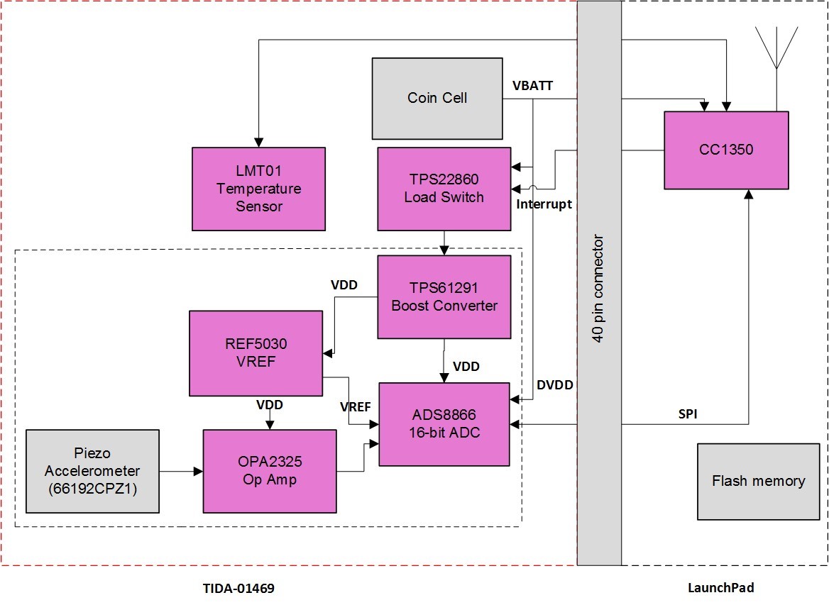
The Motor Monitoring Using Wireless Vibration Sensor Reference Design Enabling Preventive Maintenance demonstrates a wireless motor monitoring system that takes vibration data from the motor and locally computes a fast Fourier transform (FFT) before sending the data to another device using Bluetooth® low energy. The FFT information can monitor the health of the motor by keeping track of existing harmonics and comparing the current spectral data to that of a healthy motor. Figure 1 shows the system block diagram for this reference design.
 Figure 1 Wireless Motor Monitor System
Block Diagram
Figure 1 Wireless Motor Monitor System
Block DiagramThe load switch that gates power to the analog front end (the devices in the inner dashed-line box) enables the system to conserve power when in standby mode, waking up only periodically to take vibration measurements. Wakeup intervals as short as 30 minutes greatly increase battery life to more than 10 years using a CR2032 coin-cell battery.
Another critical component in wireless motor monitors is cost, as each motor requires its own monitor. The motor monitoring reference design reduces overall system cost by using a single microcontroller (MCU) to communicate with an analog-to-digital converter (ADC), process the data, communicate wirelessly and control when the device exits standby mode to take measurements. This reduces the need for separate MCUs for processing and wireless communication, as well as a nanotimer to control the wakeup intervals. The use of a single MCU also helps reduce the size of the system. The suggestions changed the meaning a little bit. I want to emphasize that it is the physical size of the system design that I am talking about, and I think this best does that.
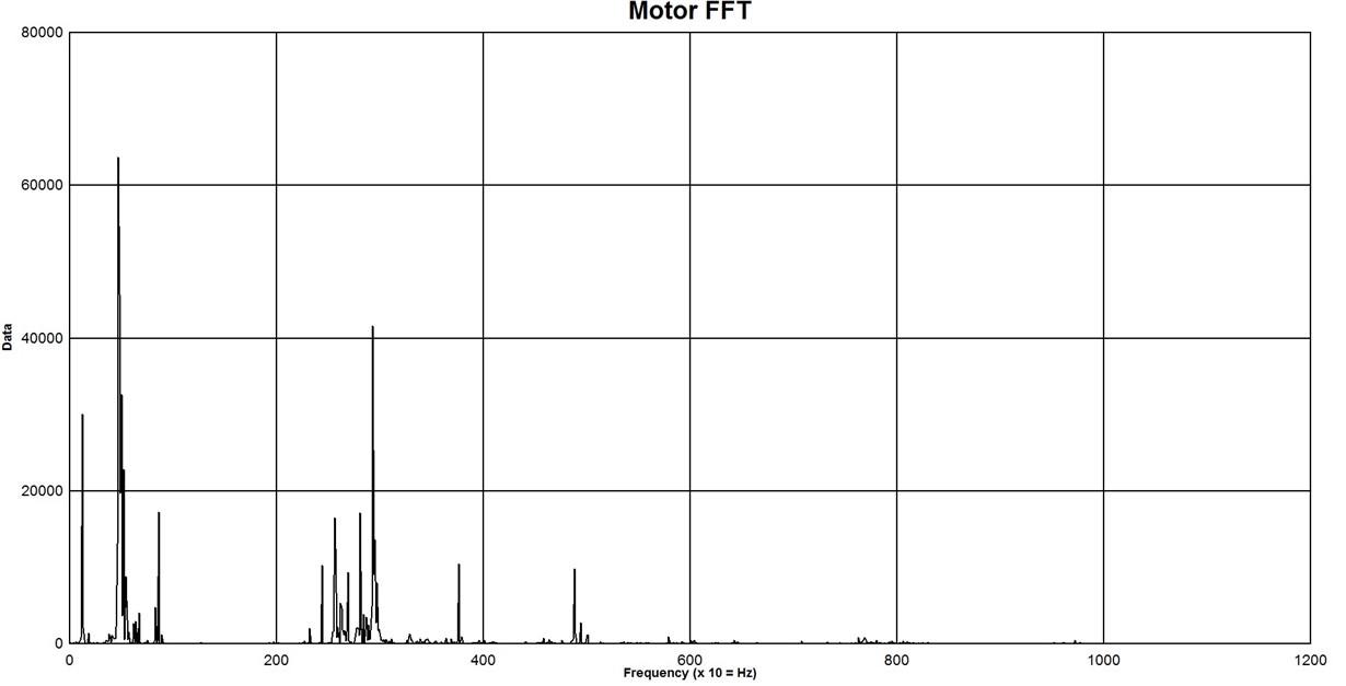
Figure 2 shows a 2K FFT of actual motor data using the motor monitoring reference design. Each value on the X-axis corresponds to 10Hz. You can see multiple harmonics present in this motor, to varying degrees.
 Figure 2 Motor FFT Data
Wireless motor monitors enable the characterization and tracking of motor health, providing large cost savings, reducing downtime and increasing motor lifetimes. Making these monitors small and wireless, with a long battery life on a single coin-cell battery, allows their placement almost anywhere without requiring regular access, while still being able to accurately and easily predict necessary maintenance.
Additional Resources:
- Learn more about how to increase battery life in wireless devices
- This Low Power Wireless PIR Motion Detector Reference Design Enabling Sensor-to-Cloud Networks demonstrates how a wireless design can have sensor-to-cloud capabilities
- Read more on predictive maintenance in building automation applications
- Check out other MCUs here