SSZTBC7 May 2016 UC1825 , UC1834-SP , UC1842A-SP , UC1843-SP , UC1843A-SP , UC1844A-SP , UC1845A-SP , UC1846-SP
Ringing in switching power supplies can generate radiated and conducted noise, create circuit jitter and excessive dissipation, and easily overstress components. Ringing is a major concern in applications such as audio, processor power and any design that requires electromagnetic interference (EMI) qualification.
Often, you can tame the circuit by adding a simple resistor-capacitor (R-C) snubber to “damp out the ringing.” In this post, I’ll outline a seven-step procedure that can help take the guesswork out of selecting your snubber values.
Ringing can occur in any switching converter where an inductance and a capacitance form an inductor-capacitor (L-C) tank. The inductance may be from component leads, printed circuit board traces and transformer leakage, while the capacitance may be due to nonlinear components such as rectifiers and interwinding transformer capacitance. The ring frequency and amplitude are generally unknown since most circuit parasitics are typically unknown. Two common locations where excessive ringing occurs (at least in converters such as a flyback) are across the rectifier diode and the switching FET. One simple solution to reduce this ringing is by damping or “snubbing” it with a series R-C circuit, typically placed directly across the rectifier or FET.
The seven-step procedure shown in Table 1 uses a common methodology that shifts the resonant frequency of the ringing to calculate the circuit’s parasitic capacitance (Co) and inductance (L). Once you know those, you can calculate the snubber capacitor (Csnub) and resistor (Rsnub). I took the example waveforms in Figure 1 and Figure 3 with an R-C snubber placed in parallel with the rectifier in the 9Vdc-57Vdc Input, 56V/20W Isolated Flyback Reference Design, but the procedure is the same if used across the FET.
 and Frequency-shifted Ringing (Bottom)") Figure 1 Unsnubbed Rectifier Ringing
(Top) and Frequency-shifted Ringing (Bottom)
Figure 1 Unsnubbed Rectifier Ringing
(Top) and Frequency-shifted Ringing (Bottom)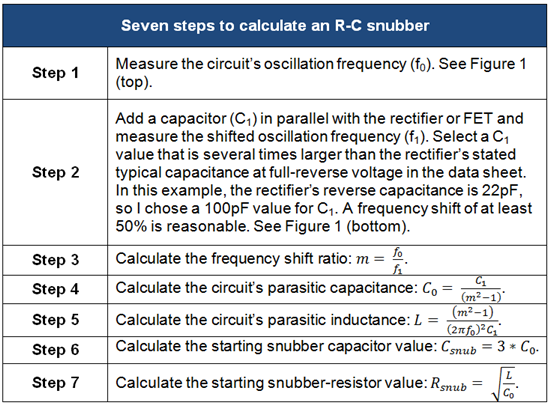
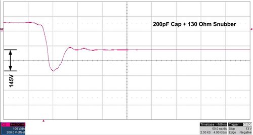
Figure 3 shows the spike reduction and damping effect of the calculated values. You can adjust the ringing higher or lower by varying the Csnub value. Larger values for Csnub reduce the voltage-spike amplitude further, but increase power loss in Rsnub.
Alternatively, you can decrease the power dissipation in Rsnub by lowering Csnub, but ringing will increase. You must weigh the trade-off between acceptable voltage-ring amplitude and Rsnub losses.
Undamped ringing in switching converters can create excessive EMI and overstress components. A properly calculated R-C snubber can be instrumental in taming these issues. I hope you’ll find my seven-step procedure simple to follow and a good starting point to help you damp out the ringing. For more about the topic covered here, see my EETimes Power Tips post Calculating an R-C snubber.