SSZTCI9 july 2015 TPD1E05U06 , TPD4E05U06 , TPD5S116 , TPD6E05U06
I was walking around the television section of my local electronics retailer when I noticed that the majority of the televisions had 4k resolution. I also noticed that my favorite fictional political drama show was available in 4k streaming. If my shopping experience alone is a good gauge, it seems that 4k content and the devices to support it are proliferating in the market.
To support all this 4k content, the newest HDMI standard, HDMI 2.0, was introduced in September 2013 by the HDMI Forum. It has many advantages over HDMI 1.4, but it also adds circuit protection design challenges.
The Differences between HDMI 2.0 and HDMI 1.4
Both standards support the same connector, so what benefits does HDMI 2.0 bring to consumers?
- 4k resolution at 50/60 frames per second (fps) versus HDMI 1.4’s 4k resolution at 24fps.
- Up to 32 audio channels (for a multidimensional, immersive audio experience).
- Dual video screens simultaneously displayed to the same screen in 1080p.
- Simultaneous delivery of multistream audio to as many as four users.
- Support for wide-angle 21:9 video aspect ratio.
- Dynamic synchronization of video and audio streams.
- Consumer electronic control (CEC) 2.0 provides expanded command and control of consumer electronics devices through a single remote.
The introduction of these additional features has bumped the overall data rate of HDMI 2.0 up to 18Gbps from 10Gbps in HDMI 1.4. This increase in data rate is great for adding additional features for the consumer, but it presents challenges when selecting the appropriate electrostatic discharge (ESD) protection diode during circuit protection design.
Key parameters for selecting ESD protection diodes for HDMI 2.0 include:
-
Parasitic capacitance. In HDMI 2.0, high-speed transition-minimized differential signaling (TMDS) lines show the increases in data rate. TMDS lines for HDMI 2.0 have a maximum data rate of 6Gbps versus 3.4Gbps in HDMI 1.4. Parasitic capacitance becomes one of the most important parameters in selecting an ESD protection diode to ensure the signal integrity of TMDS lines.
When selecting an ESD protection diode for HDMI 2.0, always consider the input/output (I/O) capacitance of the diode first. Make sure that the diode’s capacitance fits into the capacitance budget allowed for TMDS lines. When selecting, look for an I/O capacitance of less than 0.5pF.
Also consult the eye diagram included in the data sheet. This will give you a good indication of the performance of the ESD device in an HDMI 2.0 system. Figure 1 is an example eye diagram.
 Eye Diagram of TPD4E05U06 ESD Protection
Device") Figure 1 HDMI 2.0 Test Point 1
(TP1) Eye Diagram of TPD4E05U06 ESD Protection
Device
Figure 1 HDMI 2.0 Test Point 1
(TP1) Eye Diagram of TPD4E05U06 ESD Protection
Device -
Clamping voltage and RDYN. Lower capacitance is not the only parameter to consider when selecting an ESD protection diode for HDMI. With system processors moving to lower voltage nodes, there is an increased risk of failure from electrical overstress (EOS) during an ESD strike. When considering an ESD protection diode, always look at the clamping voltage and RDYN of the device.
The clamping voltage is the voltage that the ESD diode clamps to during an ESD strike. This is one of the most important parameters for ESD protection device because it is what voltage the system side of the connector will see during an ESD strike.
The datasheet lists different ways to specify the clamping voltage of an ESD device. Some devices will specify clamping voltage by using a transmission-line pulse (TLP) test. Current levels for the TLP test can range from 1A to 16A. Others specify the clamping voltage at 30ns during an 8kV IEC 61000-4-2 contact test. With all of these different ways to define clamping voltage, it can be confusing when comparing ESD protection diodes.
 Diode") Figure 2 Current versus Voltage
Curve for a Transient Voltage Suppression (TVS) Diode
Figure 2 Current versus Voltage
Curve for a Transient Voltage Suppression (TVS) DiodeOne general rule of thumb when selecting ESD protection diodes is the lower the RDYN, the lower the clamping voltage. The dynamic resistance is the effective resistance of the diode’s path to ground during an ESD strike. Shown in Equation 1, RDYN is proportionally related to the clamping voltage. It is also represented as the slope of the diode’s I-V curve in Figure 2. There are other factors such as breakdown voltage and parasitic capacitance. Nevertheless, lower dynamic resistance leads to better clamping-voltage performance for the diode.
Equation 1.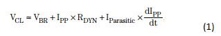
When selecting ESD protection diodes for HDMI 2.0 designs, look for two main things: capacitance and RDYN. Low parasitic capacitance will ensure that that the design will be able to preserve the HDMI 2.0 signal integrity. Low RDYN to ensure a low clamping voltage during an ESD strike. Consider these parameters to keep the system safe and the 4k content rolling.
Additional Resources
- Check out TI’s High-Definition Multimedia Interface (HDMI) ESD protection products.
- Download these documents for more information about ESD protection: