SWAY033A december 2020 – december 2020 LMG3410R050 , TMS320F280025 , TMS320F280025-Q1 , TMS320F280049 , TMS320F280049-Q1 , TMS320F28377D , TMS320F28377D-Q1 , TMS320F28377S , TMS320F28377S-Q1 , TMS320F28384D-Q1 , TMS320F28384S-Q1 , TMS320F28386D-Q1 , TMS320F28386S-Q1 , TMS320F28388D , TMS320F28P650DH , TMS320F28P650DK , TMS320F28P650SH , TMS320F28P650SK , TMS320F28P659DH-Q1 , TMS320F28P659DK-Q1 , TMS320F28P659SH-Q1
Peak current mode control for high-voltage to low-voltage DC/DC converters
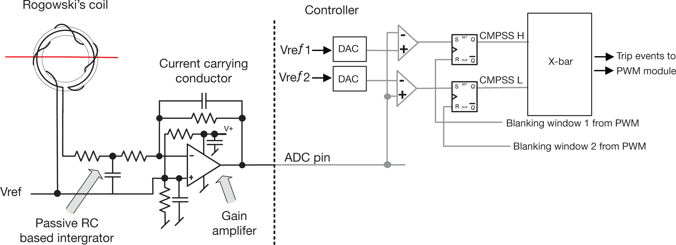
Looking at the OBC DC/DC stage, an isolated DC/DC converter such as CLLLC is a popular choice as it has an extended zero voltage switching (ZVS) range that provides soft-switching capability to enable higher switching frequency which enables smaller magnetic size. Further, a synchronous rectification scheme (Figure 3) can enable efficiency improvements of as much as 2%, but this scheme is challenging to implement and often requires external circuitry. The integrated comparator subsystems on C2000 MCUs enable the implementation of synchronous rectification without external components such as DACs, comparators or logic gates. Furthermore, the Type-4 PWM allows additional blanking windows during PWM periods and can latch the current crossing events to add robustness to the synchronous rectification scheme, thus adding noise resiliency to the implementation.
 Figure 3 Active Synchronous Rectification Scheme with On-chip
Resources for High-frequency Converters.
Figure 3 Active Synchronous Rectification Scheme with On-chip
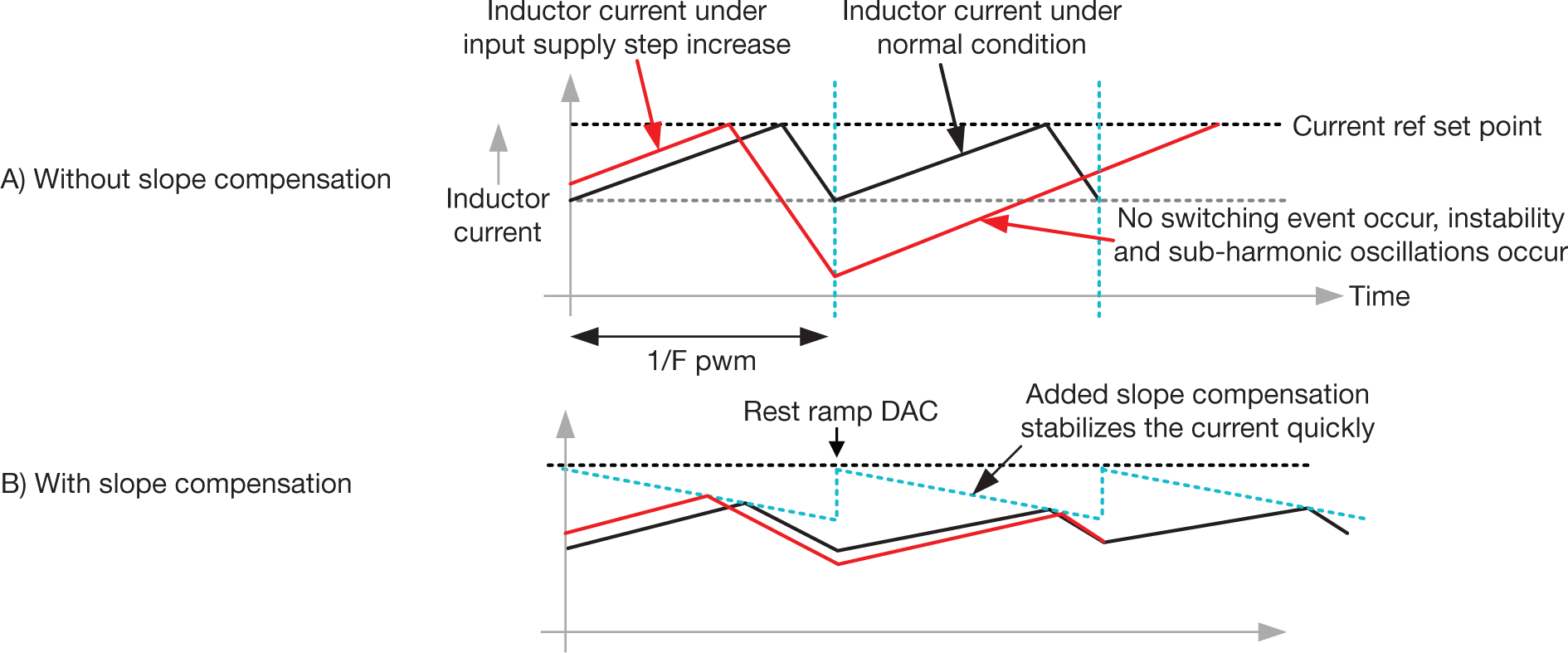
Resources for High-frequency Converters.Looking at the high-voltage to low-voltage DC/DC converter, phase-shifted full bridge (PSFB) is a typical topology used. Peak current-mode control eliminates the need for an expensive DC blocking capacitor. The primary challenge in implementing peak current-mode control is that it can lead to system instability, as shown in Figure 4. Slope compensation is added to the peak current reference point, to avoid this instability and is typically implemented in analog.
 Figure 4 Peak Current-mode Control Implementation with Slope
Compensation.
Figure 4 Peak Current-mode Control Implementation with Slope
Compensation.The advanced analog integration in the C2000 real-time MCU comparator subsystem enables achieving this advanced control with a digital controller. Additionally, Type-4 PWM features such as inserting deadband when a peak current event occurs allows the digital controller to generate complimentary PWM. This allows the change of deadband under different line and load conditions to maintain soft switching. Digital control also enables additional functions such as precharging the traction inverter bus using the high voltage to low voltage DC/DC converter, which can eliminate the need for external precharge resistors and further reduce components in the powertrain.