SLYA066 October 2022 LDC3114-Q1 , TMAG5170-Q1 , TMAG5173-Q1
Application Brief
What is automotive HMI?
Modern vehicles have many different settings to control the center console whether for music, air control, or an integrated GPS. The buttons, dials, or methods of how a person interacts with these controls are classified as Human-Machine-Interfaces (HMI). The HMI areas of new cars can include the center console, the steering wheel, window control, and more.
Different Technologies
For the different HMI needs in a vehicle, various implementations can be used. For a button or switch, this can be done using a mechanical switch, capacitive touch button, inductive touch button, a magnetic switch or latch, or by including the button on the center console display screen. There are different benefits to each implementation and consideration must be given to the use case of the button and the desired feel. For implementations like the capacitive or inductive touch button, haptic or mechanical feedback can need to be implemented to meet the desired button feel. Adding these elements to the design is easy but requires forethought of the intended feel of the button.
When considering a dial or knob in a vehicle, these can be implemented using potentiometers, rotary encoders, or Hall-effect sensors. Rotary encoders themselves can even be made with different technologies ranging from mechanical contacts to magnetic or inductive based encoders.
A common problem with traditional HMI applications is wear and tear. Any implementation where mechanical contacts are used in an electrical circuit is a potential wear and tear concern. With many different HMI points in a vehicle, reducing the potential failure points can lead to a better user experience with fewer repairs needed over the system lifetime. This is why many consider using an alternate technology that is more robust.
Inductive Touch Buttons
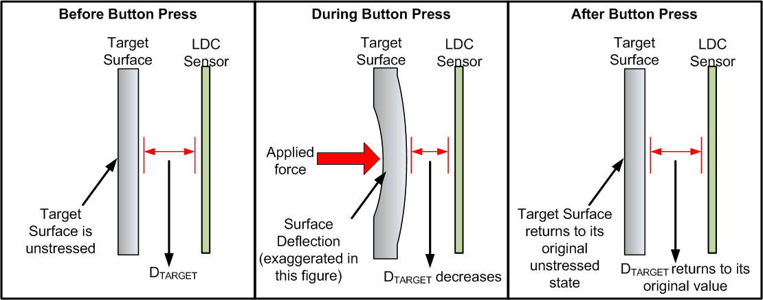
Implementing touch buttons using inductive sensing technology provides a seamless touch surface that can be used to sense the force of the press while being robust against dust, debris, and damage. Inductive touch buttons are able to do so based on the coupling between an inductive sensor coil and metal target. As the metal target bends or moves towards the sensor, the inductance on the coil changes and can be used to determine a button-press event.
 Figure 1-1 Inductive Touch Components
Because the motion of the metal causes the change in inductance, factors like gloves, dust, and dirt do not impact the button performance. Unlike some capacitive button implementations, there is no need to GND the metal target to provide consistent performance. Devices like the LDC3114-Q1 even include a button algorithm with digital outputs that signal when a press event has occurred. This algorithm also allows the button to continue working over changes in the environment like temperature and damage to the button surface. TI's LDC technology works by sensing the resonant frequency of the inductor coil when paired with a capacitor. Because of this, inductive touch buttons are also immune to nearby DC magnetic fields. For more information on inductive touch buttons, see the following Texas Instruments' references:
- LDC Device Selection Guide
- Sensor Design for Inductive Sensing Applications Using LDC
- LDC Target Design
- Design Considerations for Inductive Touch Buttons for HMIs
- Inductive Touch – Configuring LDC2114 and LDC3114 Touch-Button Sensitivity
- LDC211x and LDC3114 Internal Algorithm Functionality
- LDC2112, LDC2114 Inductive Touch System Design Guide for HMI Button Applications
- Inductive Touch Stainless Steel Keypad Reference Design for Waterproof,Noise Immune HMI Applications Reference Design
- Inductive Touch and Magnetic Dial Contactless User-Interface Reference Design
Hall-Effect Basics
Hall-effect sensors can be divided into three different types, switches, latches, and linear sensors. Switches and latches provide a digital output based on the sensed magnetic field while linear devices provide information about the magnetic field strength either through an analog output or through the device registers. Linear sensors can be sensitive to one, two, or all three axis of the magnetic field depending on the device. Each type has their benefits that can be leveraged depending on the desired use case but share some common benefits. Using Hall-effect sensors can bring high precision and accuracy to applications and work with small magnets due to high-sensitivity options. For applications such as HMI that do not need a fast sample rate, low power Hall-effect sensors can also be utilized to reduce current consumption in a system. More information on the basics of Hall-effect sensors and common applications is found in the Introduction to Hall-Effect Sensors product overview.
Hall-Effect Dial Implementation
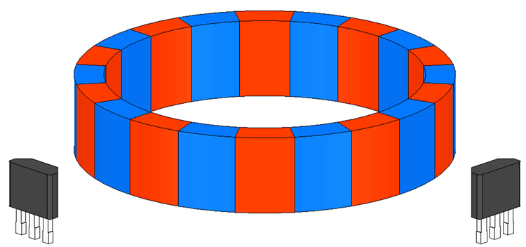
Dials in vehicles control a range of functions and can range from a simple state selector to a volume wheel. Depending on the dial functionality, the position of the dial, the change in the dial rotation, or both can be required. If only the position of the dial is required, switches can be used to give a position in discrete steps for use in a state selector. If the change in rotation is needed, latches can be used because latches provide a change in output as the magnetic field changes from north to south at the latch. Using a latch with a ring magnet can easily track the change in rotation and adding a second latch to produce a quadrature output is common among rotary encoding applications using Hall sensors.
 Figure 1-2 Quadrature Placement for Two
Hall-Effect Latches
Figure 1-2 Quadrature Placement for Two
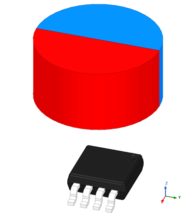
Hall-Effect LatchesThe position of the rotation can be tracked with an MCU with the latch implementation but requires the position to be saved between power cycles. More information on rotational encoding using Hall-effect latch sensors is found in the Reducing Quadrature Error for Incremental Rotary Encoding Using 2D Hall-Effect application note. Alternatively, linear sensors can be used to track the position and change in position of a magnet as it rotates. This can be done using two axis of the magnetic field and either two 1D linear Hall sensors or a single 2D or 3D linear Hall sensor.
 Figure 1-4 3D Linear Hall-Effect Sensor
Placement
Figure 1-4 3D Linear Hall-Effect Sensor
PlacementAn example of using a 3D linear sensor for an HMI dial is shown in the Inductive touch and magnetic dial contactless user-interface reference design. For more information on angle sensing using Hall sensors, see the Angle Measurement With Multi-Axis Linear Hall-Effect Sensors application report.
Hall-Effect Rocker Switch
Rocker switches are defined as having three states such as up, down, and resting in between. These switches return to the resting position unless being interacted with and can have multiple applications in the automotive space such as window control, cruise control, or the volume of a radio. Using Hall-effect sensors for this application reduces the number of mechanical contacts in the system which can improve durability by reducing the potential for wear and tear. This application can even take advantage of low-power Hall sensors to reduce current consumption. One way to implement this method is to have a magnet attached to the rocker switch and to use Hall sensors to determine if the switch is actively in position 1, position 2, or at rest in the middle of the two positions. Using two sensors for the active positions, the neutral position can be determined by the lack of output on either active position. For more information on implementing rocker switches using Hall sensors, see the HMI Rocker Switch With Hall-Effect Switches application note.