SNVS429C October 2006 – December 2016 LM3405
PRODUCTION DATA.
- 1 Features
- 2 Applications
- 3 Description
- 4 Revision History
- 5 Pin Configuration and Functions
- 6 Specifications
- 7 Detailed Description
-
8 Application and Implementation
- 8.1 Application Information
- 8.2 Typical Applications
- 8.3
System Examples
- 8.3.1 VBOOST Derived From VOUT (VIN = 12 V, IF = 1 A)
- 8.3.2 VBOOST Derived From VIN Through a Series Zener Diode, D3 (VIN = 15 V, IF = 1 A)
- 8.3.3 VBOOST Derived From VIN Through a Shunt Zener Diode, D3 (VIN = 15 V, IF = 1 A)
- 8.3.4 VBOOST Derived from VOUT Through a Series Zener Diode, D3 (VIN = 15 V, IF = 1 A)
- 9 Power Supply Recommendations
- 10Layout
- 11Device and Documentation Support
- 12Mechanical, Packaging, and Orderable Information
Package Options
Mechanical Data (Package|Pins)
- DDC|6
Thermal pad, mechanical data (Package|Pins)
Orderable Information
1 Features
- VIN Operating Range of 3 V to 15 V
- Drives up to 5 High-Brightness LEDs in Series at 1 A
- Thin SOT-6 Package
- 1.6-MHz Switching Frequency
- EN/DIM Input for Enabling and PWM Dimming of LEDs
- 300-mΩ NMOS Switch
- 40-nA Shutdown Current at VIN = 5 V
- Internally Compensated Current-mode Control
- Cycle-by-Cycle Current Limit
- Input Voltage UVLO
- Overcurrent Protection
- Thermal Shutdown
2 Applications
- LED Drivers
- Constant Current Sources
- Industrial Lighting
- LED Flashlights
3 Description
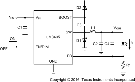
The LM3405 is a 1-A constant current buck LED driver designed to provide a simple, high efficiency solution for driving high power LEDs. With a 0.205-V reference voltage feedback control to minimize power dissipation, an external resistor sets the current as required for driving various types of LEDs. Switching frequency is internally set to 1.6 MHz, allowing small surface mount inductors and capacitors to be used. The LM3405 uses current-mode control and internal compensation offering ease of use and predictable, high performance regulation over a wide range of operating conditions. With a maximum input voltage of 15 V, the device can drive up to 3 High-Brightness LEDs in series at 1-A forward current, with the single LED forward voltage of approximately 3.7 V. Additional features include user accessible EN/DIM pin for enabling and PWM dimming of LEDs, thermal shutdown, cycle-by-cycle current limit and overcurrent protection.
Device Information(1)
| PART NUMBER | PACKAGE | BODY SIZE (NOM) |
|---|---|---|
| LM3405 | SOT (6) | 2.90 mm × 1.60 mm |
- For all available packages, see the orderable addendum at the end of the data sheet.
Typical Application Circuit

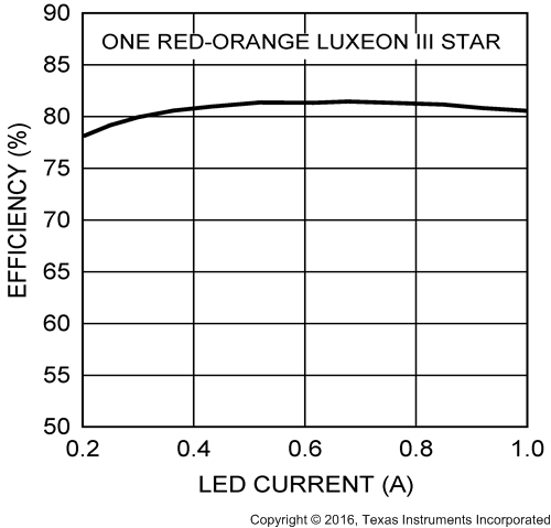
Efficiency vs LED Current (VIN = 5 V)
