SLUSBV8C August 2014 – November 2014
UNLESS OTHERWISE NOTED, this document contains PRODUCTION DATA.
- 1 Features
- 2 Applications
- 3 Description
- 4 Revision History
- 5 Device Comparison Table
- 6 Pin Configuration and Functions
- 7 Specifications
-
8 Detailed Description
- 8.1 Overview
- 8.2 Functional Block Diagram
- 8.3
Feature Description
- 8.3.1 Overvoltage-Protection (OVP) - Continuously Monitored
- 8.3.2 CHG Pin Indication (bq25101, bq25101H)
- 8.3.3 CHG Pin LED Pull-up Source (bq25101, bq25101H)
- 8.3.4 IN-DPM (VIN-DPM or IN-DPM)
- 8.3.5 OUT
- 8.3.6 ISET
- 8.3.7 PRE_TERM - Pre-Charge and Termination Programmable Threshold
- 8.3.8 TS
- 8.3.9 Timers
- 8.3.10 Termination
- 8.4 Device Functional Modes
- 9 Application and Implementation
- 10Power Supply Recommendations
- 11Layout
- 12Device and Documentation Support
- 13Mechanical, Packaging, and Orderable Information
Package Options
Mechanical Data (Package|Pins)
- YFP|6
Thermal pad, mechanical data (Package|Pins)
Orderable Information
8 Detailed Description
8.1 Overview
The bq2510x is a highly integrated family of single cell Li-Ion and Li-Pol chargers. The charger can be used to charge a battery, power a system or both. The charger has three phases of charging: pre-charge to recover a fully discharged battery, fast-charge constant current to supply the charge safely and voltage regulation to safely reach full capacity. The charger is very flexible, allowing programming of the fast-charge current and Pre-charge/Termination Current. This charger is designed to work with a USB connection (100-mA limit) or Adaptor (DC output). The charger also checks to see if a battery is present.
The charger also comes with a full set of safety features: JEITA Temperature Standard (bq25100/01/100H/101H), Over-Voltage Protection, DPM-IN, Safety Timers, and ISET short protection. All of these features and more are described in detail below.
The charger is designed for a single power path from the input to the output to charge a single cell Li-Ion or
Li-Pol battery pack. Upon application of a 5-V DC power source the ISET and OUT short checks are performed to assure a proper charge cycle.
If the battery voltage is below the LOWV threshold, the battery is considered discharged and a preconditioning cycle begins. The amount of precharge current can be programmed using the PRE-TERM pin which programs a percent of fast charge current (10 to 100%) as the precharge current. This feature is useful when the system load is connected across the battery “stealing” the battery current. The precharge current can be set higher to account for the system loading while allowing the battery to be properly conditioned. The PRE-TERM pin is a dual function pin which sets the precharge current level and the termination threshold level. The termination "current threshold" is always half of the precharge programmed current level.
Once the battery voltage has charged to the VLOWV threshold, fast charge is initiated and the fast charge current is applied. The fast charge constant current is programmed using the ISET pin. The constant current provides the bulk of the charge. Power dissipation in the IC is greatest in fast charge with a lower battery voltage. If the IC reaches 125°C, the IC enters thermal regulation, slows the timer clock by half, and reduces the charge current as needed to keep the temperature from rising any further. Figure 17 shows the charging profile with thermal regulation. Typically under normal operating conditions, the IC’s junction temperature is less than 125°C and thermal regulation is not entered.
Once the cell has charged to the regulation voltage the voltage loop takes control and holds the battery at the regulation voltage until the current tapers to the termination threshold. The termination can be disabled if desired.
Further details are described in the Operating Modes section.
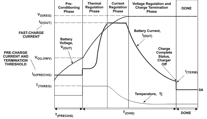 Figure 17. Charging Profile With Thermal Regulation
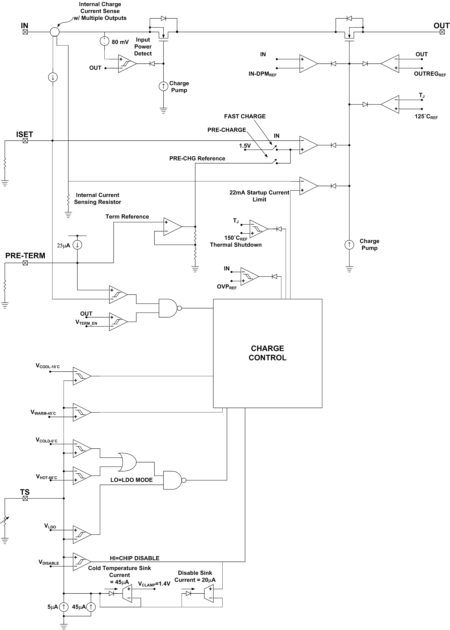
8.2 Functional Block Diagram
8.3 Feature Description
8.3.1 Overvoltage-Protection (OVP) – Continuously Monitored
If the input source applies an overvoltage, the pass FET, if previously on, turns off after a deglitch, tBLK(OVP). The timer stops counting. Once the overvoltage returns to a normal voltage, the timer and charge continues.
8.3.2 CHG Pin Indication (bq25101, bq25101H)
The charge pin has an internal open drain FET which is on (pulls down to VSS) during the first charge only (independent of TTDM) and is turned off once the battery reaches voltage regulation and the charge current tapers to the termination threshold set by the PRE-TERM resistor. The bq25101/01H terminates at 10% of the programmed charge current. The charge pin is high impedance in sleep mode and OVP and returns to its previous state once the condition is removed. Cycling input power, removing and replacing the battery, pulling the TS pin low and releasing or entering pre-charge mode causes the CHG pin to go reset (go low if power is good and a discharged battery is attached) and is considered the start of a first charge.
8.3.3 CHG Pin LED Pull-up Source (bq25101, bq25101H)
For host monitoring, a pull-up resistor is used between the CHG pin and the VCC of the host and for a visual indication a resistor in series with an LED is connected between the /CHG pin and a power source. If the CHG source is capable of exceeding 7 V, a 6.2-V zener should be used to clamp the voltage. If the source is the OUT pin, note that as the battery changes voltage, and the brightness of the LEDs vary.
8.3.4 IN-DPM (VIN-DPM or IN-DPM)
The IN-DPM feature is used to detect an input source voltage that is folding back (voltage dropping), reaching its current limit due to excessive load. When the input voltage drops to the VIN-DPM threshold the internal pass FET starts to reduce the current until there is no further drop in voltage at the input. This would prevent a source with voltage less than VIN-DPM to power the out pin. This is an added safety feature that helps protect the source from excessive loads. This feature is not applicable for bq25100A.
8.3.5 OUT
The Charger’s OUT pin provides current to the battery and to the system, if present. This IC can be used to charge the battery plus power the system, charge just the battery or just power the system (TTDM) assuming the loads do not exceed the available current. The OUT pin is a current limited source and is inherently protected against shorts. If the system load ever exceeds the output programmed current threshold, the output will be discharged unless there is sufficient capacitance or a charged battery present to supplement the excessive load.
8.3.6 ISET
An external resistor is used to Program the Output Current (10 to 250 mA) and can be used as a current monitor.
Where:
IOUT is the desired fast charge current;
KISET is a gain factor found in the electrical specification
For greater accuracy at lower currents, part of the sense FET is disabled to give better resolution. Going from higher currents to low currents, there is hysteresis and the transition occurs around 50 mA.
The ISET resistor is short protected and will detect a resistance lower than ≉420 Ω. The detection requires at least 50 mA of output current. If a “short” is detected, then the IC will latch off and can be reset by cycling the power or cycling TS pin. The OUT current is internally clamped to a maximum current of 600 mA typical and is independent of the ISET short detection circuitry.
For charge current that is below 50 mA, an extra RC circuit is recommended on ISET to acheive more stable current signal. More detail is available in 9.1 Application Information.
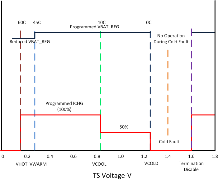 Figure 18. Operation Over TS Bias Voltage - bq25100, bq25100H, bq25101, bq25101H
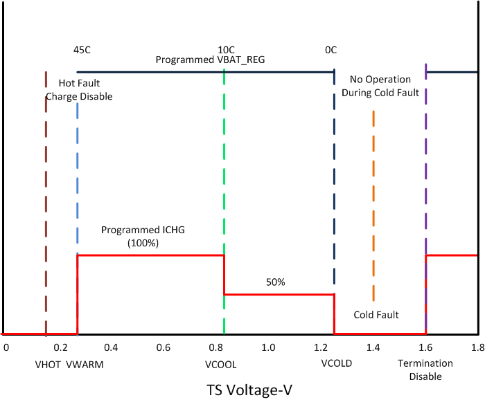 Figure 19. Operation Over TS Bias Voltage – bq25100A
8.3.7 PRE_TERM – Pre-Charge and Termination Programmable Threshold
Pre-Term is used to program both the pre-charge current and the termination current threshold. The pre-charge current level is a factor of two higher than the termination current level. The termination can be set between 5 and 50% (recommended range) of the programmed output current level set by ISET. If left floating the termination and pre-charge are set internally at 10/20% respectively. The RPRE-TERM is ranged from 600 Ω to 30 kΩ and the minimum termination current can be programmed to 1 mA. The pre-charge-to-fast-charge, Vlowv threshold is set to 2.5 V.
Where:
%Term is the percent of fast charge current where termination occurs;
%Pre-CHG is the percent of fast charge current that is desired during precharge;
KTERM and KPRE-CHG are gain factors found in the electrical specifications.
8.3.8 TS
The TS function for the bq2510x family is designed to follow the new JEITA temperature standard (bq25100/bq25100H/bq25101/bq25101H) for Li-Ion and Li-Pol batteries. There are now four thresholds, 60°C, 45°C, 10°C, and 0°C. Normal operation occurs between 10°C and 45°C. If between 0°C and 10°C the charge current level is cut in half and if between 45°C and 60°C the regulation voltage is reduced to 4.1 V max for bq25100 and 4.2 V max for bq25100H, see Figure 18. The TS function for the bq25100A cut the charge current level in half between 0°C and 10°C and disables charging when the NTC temperature is above 45°C.
The TS feature is implemented using an internal 50μA current source to bias the thermistor (designed for use with a 10-k NTC β = 3370 (SEMITEC 103AT-2 or Mitsubishi TH05-3H103F) connected from the TS pin to VSS. If this feature is not needed, a fixed 10-k can be placed between TS and VSS to allow normal operation. This may be done if the host is monitoring the thermistor and then the host would determine when to pull the TS pin low to disable charge.
The TS pin has two additional features, when the TS pin is pulled low or floated/driven high. A low disables charge and a high puts the charger in TTDM.
Above 60°C (45°C for bq25100A) or below 0°C the charge is disabled. Once the thermistor reaches ≉–10°C the TS current folds back to keep a cold thermistor (between –10°C and –50°C) from placing the IC in the TTDM mode. If the TS pin is pulled low into disable mode, the current is reduce to ≉30 μA. Since the ITS curent is fixed along with the temperature thresholds, it is not possible to use thermistor values other than the 10-k NTC (at 25°C).
8.3.9 Timers
The pre-charge timer is set to 30 minutes. The pre-charge current, can be programmed to off-set any system load, making sure that the 30 minutes is adequate.
The fast charge timer is fixed at 10 hours and can be increased real time by going into thermal regulation or IN-DPM. The timer clock slows by a factor of 2, resulting in a clock than counts half as fast when in these modes. If either the 30 minute or ten hour timer times out, the charging is terminated and for bq25101/1H the CHG pin goes high impedance if not already in that state. The timer is reset by disabling the IC, cycling power or going into and out of TTDM.
8.3.10 Termination
Once the OUT pin goes above VRCH, (reaches voltage regulation) and the current tapers down to the termination threshold, a battery detect route is run to determine if the battery was removed or the battery is full. If the battery is present, the charge current will terminate. If the battery was removed along with the thermistor, then the TS pin is driven high and the charge enters TTDM. If the battery was removed and the TS pin is held in the active region, then the battery detect routine will continue until a battery is inserted. The termination current can be programmed down to 625 uA, however, the accuracy will reduce acoordingly when the termination current is below 1 mA.
8.4 Device Functional Modes
8.4.1 Power-Down or Undervoltage Lockout (UVLO)
The bq2510x family is in power down mode if the IN pin voltage is less than UVLO. The part is considered “dead” and all the pins are high impedance. Once the IN voltage rises above the UVLO threshold the IC will enter Sleep Mode or Active mode depending on the OUT pin (battery) voltage.
8.4.2 Power-up
The IC is alive after the IN voltage ramps above UVLO (see sleep mode), resets all logic and timers, and starts to perform many of the continuous monitoring routines. Typically the input voltage quickly rises through the UVLO and sleep states where the IC declares power good, starts the qualification charge at 22 mA, sets the charge current base on the ISET pin, and starts the safety timer.
8.4.3 Sleep Mode
If the IN pin voltage is between VOUT+VDT and UVLO, the charge current is disabled, the safety timer counting stops (not reset). As the input voltage rises and the charger exits sleep mode, the safety timer continues to count and the charge is enabled. See Figure 20.
8.4.4 New Charge Cycle
A new charge cycle is started when a good power source is applied, performing a chip disable/enable (TS pin), exiting Termination and Timer Disable Mode (TTDM), detecting a battery insertion or the OUT voltage dropping below the VRCH threshold.
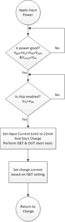 Figure 20. bq2510x Power-Up Flow Diagram
8.4.5 Termination and Timer Disable Mode (TTDM) - TS Pin High
The battery charger is in TTDM when the TS pin goes high from removing the thermistor (removing battery pack/floating the TS pin) or by pulling the TS pin up to the TTDM threshold.
When entering TTDM, the 10 hour safety timer is held in reset and termination is disabled. A battery detect routine is run to see if the battery was removed or not. For bq25101/1H, if the battery was removed then the CHG pin will go to its high impedance state if not already there. If a battery is detected the CHG pin does not change states until the current tapers to the termination threshold, where the CHG pin goes to its high impedance state if not already there (the regulated output will remain on).
The charging profile does not change (still has pre-charge, fast-charge constant current and constant voltage modes). This implies the battery is still charged safely and the current is allowed to taper to zero.
When coming out of TTDM, the battery detect routine is run and if a battery is detected, then a new charge cycle begins.
If TTDM is not desired upon removing the battery with the thermistor, one can add a 237-kΩ resistor between TS and VSS to disable TTDM. This keeps the current source from driving the TS pin into TTDM. This creates ≉0.1°C error at hot and a ≉3°C error at cold.
8.4.6 Battery Detect Routine
The battery detect routine should check for a missing battery while keeping the OUT pin at a useable voltage.
The battery detect routine is run when entering and exiting TTDM to verify if battery is present, or run all the time if battery is missing and not in TTDM. On power-up, if battery voltage is greater than VRCH thereshold, a battery detect routine is run to determine if a battery is present.
The battery detect routine is disabled while the IC is in TTDM, or has a TS fault. See Figure 21 for the Battery Detect Flow Diagram.
8.4.7 Refresh Threshold
After termination, if the OUT pin voltage drops to VRCH (100mV below regulation) then a new charge is initiated.
8.4.8 Starting a Charge on a Full Battery
The termination threshold is raised by ≉14% for the first minute of a charge cycle so if a full battery is removed and reinserted or a new charge cycle is initiated, that the new charge terminates (less than 1 minute). Batteries that have relaxed many hours may take several minutes to taper to the termination threshold and terminate charge.
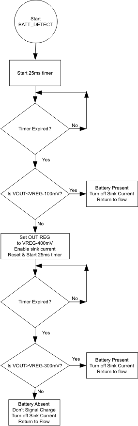 Figure 21. Battery Detect Routine