SLUSA91C October 2010 – October 2015
PRODUCTION DATA.
- 1 Features
- 2 Applications
- 3 Description
- 4 Revision History
- 5 Pin Configuration and Functions
-
6 Specifications
- 6.1 Absolute Maximum Ratings
- 6.2 ESD Ratings
- 6.3 Recommended Operating Conditions
- 6.4 Thermal Information
- 6.5 Electrical Characteristics: Supply Current
- 6.6 Power-On Reset (POR)
- 6.7 Wake From Sleep
- 6.8 RBI RAM Backup
- 6.9 3.3-V Regulator
- 6.10 2.5-V Regulator
- 6.11 PRES, SMBD, SMBC
- 6.12 CHG, DSG FET Drive
- 6.13 PCHG FET Drive
- 6.14 FUSE
- 6.15 Coulomb Counter
- 6.16 VC1, VC2, VC3, VC4
- 6.17 TS1, TS2
- 6.18 Internal Temperature Sensor
- 6.19 Internal Thermal Shutdown
- 6.20 High-Frequency Oscillator
- 6.21 Low-Frequency Oscillator
- 6.22 Internal Voltage Reference
- 6.23 Flash
- 6.24 OCD Current Protection
- 6.25 SCD1 Current Protection
- 6.26 SCD2 Current Protection
- 6.27 SCC Current Protection
- 6.28 SBS Timing Requirements
- 6.29 Typical Characteristics
- 7 Parameter Measurement Information
- 8 Detailed Description
- 9 Application and Implementation
- 10Power Supply Recommendations
- 11Layout
- 12Device and Documentation Support
- 13Mechanical, Packaging, and Orderable Information
Package Options
Mechanical Data (Package|Pins)
- DBT|30
Thermal pad, mechanical data (Package|Pins)
Orderable Information
8 Detailed Description
8.1 Overview
The bq3055 device measures the voltage, temperature, and current to determine battery capacity and state-of-charge (SOC). The bq3050 monitors charge and discharge activity by sensing the voltage across a small value resistor (5 mΩ to 20 mΩ, typical) between the SRP and SRN pins and in series with the battery. By integrating charge passing through the battery, the battery’s SOC is adjusted during battery charge or discharge. Measurements of OCV and charge integration determine chemical SOC.
The Qmax values are taken from a cell manufacturers' data sheet multiplied by the number of parallel cells, and is also used for the value in Design Capacity. It uses the OCV and Qmax value to determine StateOfCharge() on battery insertion, device reset, or on command. The FullChargeCapacity() is reported as the learned capacity available from full charge until Voltage() reaches the EDV0 threshold. As Voltage() falls below the Shutdown Voltage for Shutdown Time and has been out of SHUTDOWN mode for at least Shutdown Time, the PF Flags1 () [VSHUT] bit is set. For additional details, see bq3055 Technical Reference Manual (SLUU440).
Fuel gauging is derived from the Compensated End of Discharge Voltage (CEDV) method, which uses a mathematical model to correlate remaining state of charge (RSOC) and voltage near to the end of discharge state. This requires a full-discharge cycle for a single-point FCC update. The implementation models cell voltage (OCV) as a function of battery SOC, temperature, and current. The impedance is also a function of SOC and temperature, which can be satisfied by using seven parameters: EMF, C0, R0, T0, R1, TC, and C1.
8.1.1 Configuration
8.1.1.1 Oscillator Function
The bq3055 fully integrates the system oscillators and does not require any external components to support this feature.
8.1.1.2 System Present Operation
The bq3055 checks the PRES pin periodically (1 s). If PRES input is pulled to ground by the external system, the bq3055 detects this as system present.
8.1.1.3 2-, 3-, or 4-Cell Configuration
In a 2-cell configuration, VC1 is shorted to VC2 and VC3. In a 3-cell configuration, VC1 is shorted to VC2.
8.1.1.4 Cell Balancing
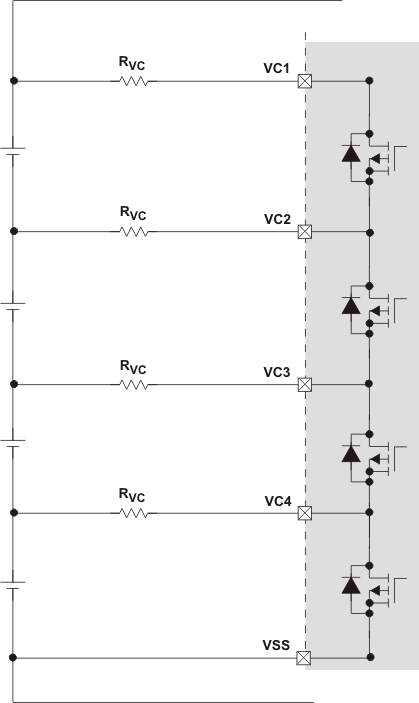
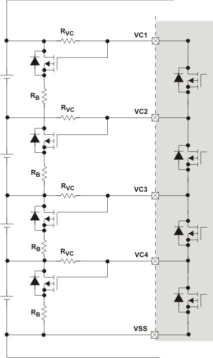
The device supports cell balancing by bypassing the current of each cell during charging or at rest. If the device's internal bypass is used, up to 10 mA can be bypassed and multiple cells can be bypassed at the same time. Higher cell balance current can be achieved by using an external cell balancing circuit. In external cell balancing mode, only one cell at a time can be balanced.
The cell balancing algorithm determines the amount of charge needed to be bypassed to balance the capacity of all cells.
8.1.1.4.1 Internal Cell Balancing
When internal cell balancing is configured, the cell balance current is defined by the external resistor RVC at the VCx input. See Figure 4.
 Figure 4. Internal Cell Balancing with RVC
8.1.1.4.2 External Cell Balancing
When external cell balancing is configured, the cell balance current is defined by RB. See Figure 5. Only one cell at a time can be balanced.
 Figure 5. External Cell Balancing with RB
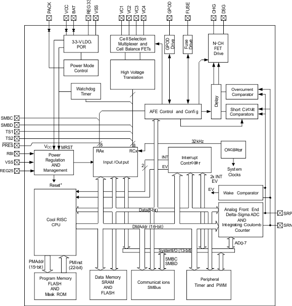
8.2 Functional Block Diagram

8.3 Feature Description
8.3.1 Primary (1st Level) Safety Features
The bq3055 supports a wide range of battery and system protection features that can easily be configured. The primary safety features include:
- Cell Overvoltage and Undervoltage Protection
- Charge and Discharge Overcurrent
- Short-Circuit
- Charge and Discharge Overtemperature
- AFE Watchdog
8.3.2 Secondary (2nd Level) Safety Features
The secondary safety features of the bq3055 can be used to indicate more serious faults through the FUSE pin. This pin can be used to blow an in-line fuse to permanently disable the battery pack from charging or discharging. The secondary safety protection features include:
- Safety Overvoltage
- Safety Overcurrent in Charge and Discharge
- Safety Overtemperature in Charge and Discharge
- Charge FET, Discharge FET, and Precharge FET Faults
- Cell Imbalance Detection
- Fuse Blow by Secondary Voltage Protection IC
- AFE Register Integrity Fault (AFE_P)
- AFE Communication Fault (AFE_C)
8.3.3 Charge Control Features
The bq3055 charge control features include:
- Supports JEITA temperature ranges. Reports charging voltage and charging current according to the active temperature range
- Handles more complex charging profiles. Allows for splitting the standard temperature range into two sub-ranges and allows for varying the charging current according to the cell voltage
- Reports the appropriate charging current needed for constant current charging and the appropriate charging voltage needed for constant voltage charging to a smart charger using SMBus broadcasts
- Reduce the charge difference of the battery cells in fully charged state of the battery pack gradually using a voltage-based cell balancing algorithm during charging. A voltage threshold can be set up for cell balancing to be active. This prevents fully charged cells from overcharging and causing excessive degradation and also increases the usable pack energy by preventing premature charge termination.
- Supports precharging and zero-volt charging
- Supports charge inhibit and charge suspend if battery pack temperature is out of temperature range
- Reports charging fault and also indicate charge status through charge and discharge alarms
8.3.4 Gas Gauging
The bq3055 uses the CEDV algorithm to measure and calculate the available capacity in battery cells. The bq3055 accumulates a measure of charge and discharge currents and compensates the charge current measurement for the temperature and state-of-charge of the battery. The bq3055 estimates self-discharge of the battery and also adjusts the self-discharge estimation based on temperature. See the bq3055 Technical Reference Manual (SLUU440) for further details.
8.3.5 Lifetime Data Logging Features
The bq3055 offers limited lifetime data logging for the following critical battery parameters:
- Lifetime Maximum Temperature
- Lifetime Minimum Temperature
- Lifetime Maximum Battery Cell Voltage
- Lifetime Minimum Battery Cell Voltage
8.3.6 Authentication
- The bq3055 supports authentication by the host using SHA-1.
- SHA-1 authentication by the gas gauge is required for unsealing and full access.
8.4 Device Functional Modes
The bq3055 supports three power modes to reduce power consumption:
- In NORMAL Mode, the bq3055 performs measurements, calculations, protection decisions, and data updates in 0.25-s intervals. Between these intervals, the bq3055 is in a reduced power stage.
- In SLEEP Mode, the bq3055 performs measurements, calculations, protection decisions, and data updates in adjustable time intervals. Between these intervals, the bq3055 is in a reduced power stage. The bq3055 has a wake function that enables exit from Sleep mode when current flow or failure is detected.
- In SHUTDOWN Mode, the bq3055 is completely disabled.