SNVS572E July 2008 – January 2016 LM25037 , LM25037-Q1
PRODUCTION DATA.
- 1 Features
- 2 Applications
- 3 Description
- 4 Revision History
- 5 Pin Configuration and Functions
- 6 Specifications
- 7 Detailed Description
- 8 Application and Implementation
- 9 Power Supply Recommendations
- 10Layout
- 11Device and Documentation Support
- 12Mechanical, Packaging, and Orderable Information
Package Options
Mechanical Data (Package|Pins)
- PW|16
Thermal pad, mechanical data (Package|Pins)
Orderable Information
1 Features
- Qualified for Automotive Applications
- AEC-Q100 Qualified With the Following Results:
- Device Temperature Grade 1: –40°C to +125°C Operating Junction Temperature
- Device HBM ESD Classification Level 2
- Device CDM ESD Classification Level C4B
- Alternating Outputs for Double-Ended Topologies
- Ultra Wide Input Operating Range from 5.5 V to 75 V
- Current-Mode or Feed-Forward Voltage-Mode Control
- Programmable Maximum Duty Cycle Limit
- 2% Feedback Reference Accuracy
- High Gain-Bandwidth Error Amplifier
- Programmable Line Undervoltage Lockout (UVLO) With Adjustable Hysteresis
- Versatile Dual Mode Overcurrent Protection With Hiccup Delay Timer
- Programmable Soft-Start
- Precision 5-V Reference Output
- Current Sense Leading Edge Blanking
- Resistor Programmed 2-MHz Capable Oscillator
- Oscillator Synchronization Capability With Low-Frequency Lockout Protection
- 16-Pin TSSOP
2 Applications
- Telecom Power Converters
- Industrial Power Converters
- Automotive Power Converters (Q1 Version)
3 Description
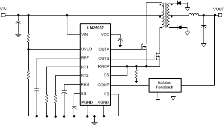
The LM25037 PWM controller contains all the features necessary to implement balanced double-ended power converter topologies, such as push-pull, half-bridge and full-bridge. These double-ended topologies allow for higher efficiencies and greater power densities compared to common single-ended topologies such as the flyback and forward. The LM25037 can be configured for either voltage mode or current mode control with minimum external components. Two alternating gate drive outputs are provided, each capable of 1.2-A peak output current. The LM25037 can be configured to operate directly from the input voltage rail over an ultra-wide range of 5.5 V to 75 V. Additional features include programmable maximum duty cycle limit, line undervoltage lockout, cycle-by-cycle current limit and a hiccup mode fault protection with adjustable timeout delay, soft-start and a 2-MHz capable oscillator with synchronization capability, precision reference and thermal shutdown.
Device Information(1)
| PART NUMBER | PACKAGE | BODY SIZE (NOM) |
|---|---|---|
| LM25037 LM25037-Q1 |
TSSOP (16) | 5.00 mm × 4.40 mm |
- For all available packages, see the orderable addendum at the end of the data sheet.
Simplified Push-Pull Power Converter
