SNVS250F November 2004 – February 2016 LM3670
PRODUCTION DATA.
- 1 Features
- 2 Applications
- 3 Description
- 4 Revision History
- 5 Connection Diagram
- 6 Specifications
- 7 Detailed Description
- 8 Application and Implementation
- 9 Power Supply Recommendations
- 10Layout
- 11Device and Documentation Support
- 12Mechanical, Packaging, and Orderable Information
Package Options
Mechanical Data (Package|Pins)
- DBV|5
Thermal pad, mechanical data (Package|Pins)
Orderable Information
7 Detailed Description
7.1 Overview
The LM3670, a high-efficiency step-down DC-DC switching buck converter, delivers a constant voltage from either a single Li-Ion or three-cell NiMH/NiCd battery to portable devices such as cell phones and PDAs. Using a voltage mode architecture with synchronous rectification, the LM3670 can deliver up to 350 mA depending on the input voltage and output voltage (voltage head room), and the inductor chosen (maximum current capability).
There are three modes of operation depending on the current required: pulse width modulation (PWM), pulse frequency modulation (PFM), and shutdown. PWM mode handles current loads of approximately 70 mA or higher. Lighter output current loads cause the device to automatically switch into PFM for reduced current consumption (IQ = 15 µA typical) and a longer battery life. Shutdown mode turns off the device, offering the lowest current consumption (ISHUTDOWN = 0.1 µA typical).
The LM3670 can operate up to a 100% duty cycle (PMOS switch always on) for low dropout control of the output voltage. In this way the output voltage is controlled down to the lowest possible input voltage.
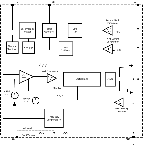
Additional features include soft-start, undervoltage lockout, current overload protection, and thermal overload protection. As shown in Figure 17, only three external power components are required for implementation.
7.2 Functional Block Diagram

7.3 Feature Description
7.3.1 Circuit Operation
The LM3670 operates as follows. During the first portion of each switching cycle, the control block in the LM3670 turns on the internal PFET switch. This allows current to flow from the input through the inductor to the output filter capacitor and load. The inductor limits the current to a ramp with a slope of:

by storing energy in a magnetic field. During the second portion of each cycle, the controller turns the PFET switch off, blocking current flow from the input, and then turns the NFET synchronous rectifier on. The inductor draws current from ground through the NFET to the output filter capacitor and load, which ramps the inductor current down with a slope of:

The output filter stores charge when the inductor current is high, and releases it when low, smoothing the voltage across the load.
7.3.2 Soft Start
The LM3670 has a soft-start circuit that limits in-rush current during start-up. Typical start-up times with a 10-µF output capacitor and 350-mA load is 400 µs:
Table 1. Typical Start-Up Times for Soft Start
| INRUSH CURRENT (mA) | DURATION (µs) |
|---|---|
| 0 | 32 |
| 70 | 224 |
| 140 | 256 |
| 280 | 256 |
| 620 | until soft start ends |
7.3.3 LDO - Low Dropout Operation
The LM3670 can operate at 100% duty cycle (no switching, PMOS switch is completely on) for low dropout support of the output voltage. In this way the output voltage is controlled down to the lowest possible input voltage.
The minimum input voltage needed to support the output voltage is
where
- ILOAD = load current
- RDSON, PFET = the drain to source resistance of PFET switch in the triode region
- RINDUCTOR = the inductor resistance
7.4 Device Functional Modes
7.4.1 PWM Operation
During PWM operation the converter operates as a voltage-mode controller with input voltage feed forward. This allows the converter to achieve excellent load and line regulation. The DC gain of the power stage is proportional to the input voltage. To eliminate this dependence, feed forward inversely proportional to the input voltage is introduced.
7.4.1.1 Internal Synchronous Rectification
While in PWM mode, the LM3670 uses an internal NFET as a synchronous rectifier to reduce rectifier forward voltage drop and associated power loss. Synchronous rectification provides a significant improvement in efficiency whenever the output voltage is relatively low compared to the voltage drop across an ordinary rectifier diode.
7.4.1.2 Current Limiting
A current limit feature allows the LM3670 to protect itself and external components during overload conditions PWM mode implements cycle-by-cycle current limiting using an internal comparator that trips at 620 mA (typical).
7.4.2 PFM Operation
At very light load, the converter enters PFM mode and operates with reduced switching frequency and supply current to maintain high efficiency.
The part automatically transition into PFM mode when either of two conditions occurs for a duration of 32 or more clock cycles:
- The inductor current becomes discontinuous
- The peak PMOS switch current drops below the IMODE level:

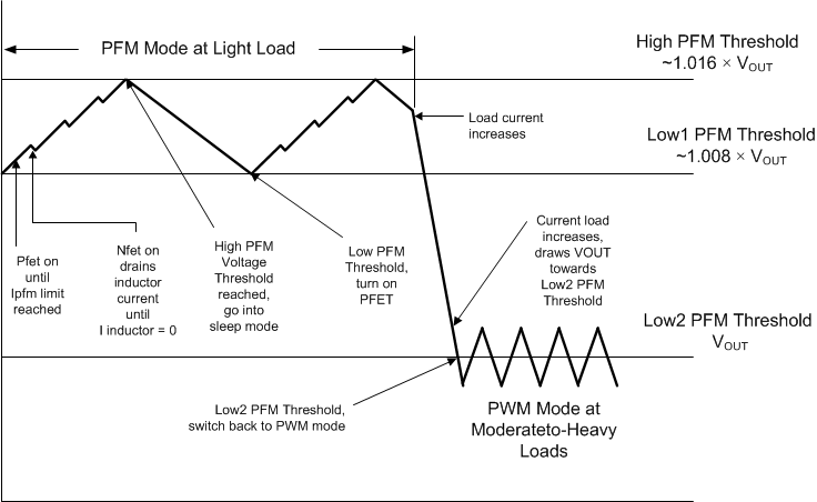
During PFM operation, the converter positions the output voltage slightly higher than the nominal output voltage in PWM operation, allowing additional headroom for voltage drop during a load transient from light to heavy load. The PFM comparator senses the output voltage via the feedback pin and control the switching of the output FETs such that the output voltage ramps between 0.8% and 1.6% (typical) above the nominal PWM output voltage. If the output voltage is below the high PFM comparator threshold, the PMOS power switch is turned on. It remains on until the output voltage exceeds the ‘high’ PFM threshold or the peak current exceeds the IPFM level set for PFM mode. The peak current in PFM mode is:

Once the PMOS power switch is turned off, the NMOS power switch is turned on until the inductor current ramps to zero. When the NMOS zero-current condition is detected, the NMOS power switch is turned off. If the output voltage is below the high PFM comparator threshold (see Figure 16), the PMOS switch is again turned on and the cycle is repeated until the output reaches the desired level. Once the output reaches the high PFM threshold, the NMOS switch is turned on briefly to ramp the inductor current to zero and then both output switches are turned off and the part enters an extremely low power mode. Quiescent supply current during this sleep mode is less than 30 µA, which allows the part to achieve high efficiencies under extremely light load conditions. When the output drops below the low PFM threshold, the cycle repeats to restore the output voltage to approximately 1.6% above the nominal PWM output voltage.
If the load current increases during PFM mode (see Figure 16) causing the output voltage to fall below the ‘low2’ PFM threshold, the part automatically transitions into fixed-frequency PWM mode.
 Figure 16. Operation in PFM Mode and Transition to PWM Mode
7.4.3 Shutdown
Setting the EN input pin low (< 0.4 V) places the LM3670 in shutdown mode. During shutdown the PFET switch, NFET switch, reference, control and bias circuitry of the LM3671 are turned off. Setting EN high (> 1.3 V) enables normal operation. It is recommended to set EN pin low to turn off the LM3671 during system power up and undervoltage conditions when the supply is less than 2.5 V. Do not leave the EN pin floating.